
PFAS Removal in Food & Beverage Production Water: Engineering the Process Water Barrier

A single undetected PFAS spike in ingredient water doesn’t just fail a lab test — it moves directly into every batch, bottle, and label claim your brand has made. Unlike a TDS excursion that scales a boiler over months, PFAS contamination enters the finished product on day one, with no visible warning at the tap.
Before evaluating any system for PFAS removal in food & beverage production water, lock down these five technical specs first:
- Verified rejection across chain lengths — not just PFOA/PFOS, but short-chain compounds like PFBS and GenX that behave very differently in treatment
- A defined fate for the captured PFAS — reject stream or spent media disposal path, not just a removal claim
- Continuous duty-cycle capacity — matched to peak ingredient-water GPM draw, not daily average GPD
- Automated CIP and media-life monitoring — breakthrough detection before contamination, not after
- Redundant train configuration — so a media change-out never forces a production stoppage
Fast Check Product: https://yourwatergood.com/product/industrial-reverse-osmosis-system/
Why “PFAS-Free” Isn’t a Single Technology: Matching Removal Method to Chain Length and Water Source
Every PFAS removal technology has a blind spot, and vendors who sell one technology as a universal fix are hiding it.
Granular Activated Carbon (GAC) adsorbs long-chain compounds like PFOA and PFOS effectively, because their higher hydrophobicity binds well to carbon. Short-chain compounds — PFBA, PFBS, GenX/HFPO-DA — are more water-soluble and pass through GAC beds with far less affinity, especially once empty-bed contact time drops below design spec.
Ion Exchange (IX) resin, particularly anion exchange media, generally outperforms GAC on short-chain species and offers a smaller footprint for the same throughput. The trade-off is capacity: resin saturates faster under high-TDS or high-sulfate feed water, and regenerable resins generate a concentrated PFAS brine that still needs a disposal path.
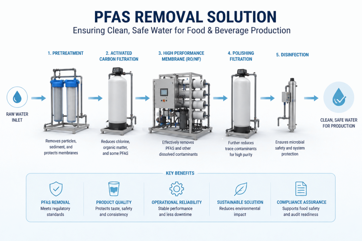
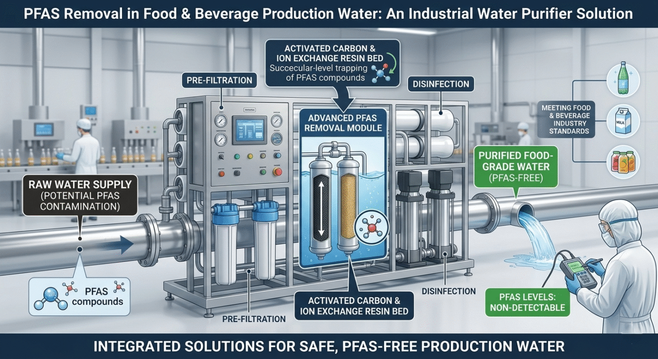
Reverse Osmosis and Nanofiltration work on size exclusion, not adsorption capacity — which makes them the only technology in this list that doesn’t lose effectiveness as chain length shortens. That’s why a properly engineered barrier train uses GAC or IX for bulk load reduction and protects a downstream RO membrane as the final polishing barrier, rather than betting the entire compliance program on one adsorption bed.
Municipal vs. well water changes the risk profile, not just the pre-treatment. Municipal systems serving 25+ connections are required to test and publicly report PFOA/PFOS under the EPA’s finalized drinking water rule — your Consumer Confidence Report is a real data source. Private industrial wells have no such requirement. A facility running its own well is operating with zero regulatory PFAS visibility unless it tests independently, on top of the usual well-water pre-treatment burden: iron, manganese, and silica fouling ahead of any membrane or adsorption stage that municipal-fed lines rarely see.
For food, beverage, and nutraceutical production specifically, ingredient water has to meet the safe-and-sanitary standard under FDA’s food safety framework — which in practice means matching or beating the EPA’s enforceable PFAS limits, not a separate food-specific PFAS threshold. Most quality teams now write that EPA benchmark directly into their internal ingredient-water spec, with margin, as a brand-protection buffer.
Pre-Engineered PFAS Barrier Skids vs. Fully Customized Turnkey Multi-Barrier Systems
A single production line with one well-characterized feed source can often run on a pre-engineered barrier skid. A facility with multiple intake points, blended municipal/well supply, or a brand-safety mandate for zero detectable PFAS needs a fully customized, multi-stage train.
| Capability | Pre-Engineered Barrier Skid | Fully Customized Turnkey Multi-Barrier System |
|---|---|---|
| Flow Capacity | Fixed configurations, typically 10–50 GPM | Engineered to spec, 5–300+ GPM |
| CAPEX Position | Lower upfront cost, single adsorption stage | Higher upfront cost, GAC/IX + RO polishing stack |
| Lead Time | Shorter — built from standard vessels | Longer — engineered and fabricated to order |
| PLC Integration | Basic HMI, manual breakthrough sampling | Full Siemens/Allen-Bradley integration, inline monitoring |
| Redundancy | Single train (N) | N+1 parallel trains, no-stop media change-out |
A single-stage skid is a reasonable starting point for a facility just beginning to characterize its PFAS exposure. Once a brand has zero-tolerance labeling claims or supplies a retailer with its own PFAS spec, the multi-barrier turnkey architecture becomes the only defensible engineering position.
The Reject Stream Problem: Where Captured PFAS Actually Goes After “Removal”
Here’s the detail most PFAS marketing conveniently skips: removing PFAS from your process water doesn’t destroy it. It concentrates it, and that concentrate becomes your problem next.
Spent GAC and IX media are saturated with the exact PFAS load they pulled out of your feed water. Depending on your state, that spent media can be classified as regulated waste, requiring off-site thermal reactivation or, increasingly, destruction technologies like supercritical water oxidation rather than simple landfill disposal.
An RO polishing stage carries the same liability in liquid form. At a typical 80% to 90% recovery rate, the reject stream concentrates PFAS to roughly five to ten times the feed concentration. Sending that concentrate to the sanitary sewer without a pretreatment permit review doesn’t solve your compliance problem — it just hands it to the municipal wastewater plant downstream, which almost certainly has no PFAS destruction capability either, and can trigger industrial discharge liability back onto your facility as the source.
The same design-stage discipline that governs winter membrane sizing applies here. If your RO polishing stage runs on well water and feed temperature drops toward 50°F (10°C) in winter, membrane flux falls and the system needs a Temperature Correction Factor — typically 30% to 40% additional membrane area — built in at the design stage. Skip it, and the pump gets forced to excessive PSI chasing flow, accelerating irreversible fouling on a membrane that’s already carrying a concentrated PFAS load.
Don’t buy a PFAS removal system without a documented answer to one question: what exactly happens to the spent media or reject stream, and who is responsible for its disposal? Request a custom water analysis review and CAD skid diagram before finalizing your specification — an incomplete disposal plan converts an engineering solution into a long-term liability on your books.
PLC Automation, Media Life-Cycle Monitoring, and 24/7 Duty-Cycle Architecture for Continuous F&B Lines
A barrier system built for continuous food and beverage production duty is engineered differently from a light-commercial adsorption cartridge in every material choice:
- 316L stainless steel skid framing and product-contact piping, rated for continuous operation without micro-fracturing under years of CIP cycling
- Siemens or Allen-Bradley PLC control logic, tracking conductivity or TOC surrogate readings as an early-warning proxy for media breakthrough before PFAS ever reaches the finished product
- Automated CIP sequencing for pre-filters and RO polishing membranes, run without halting the ingredient-water supply to the line
- Multi-media and cartridge pre-filtration ahead of both the adsorption bed and the RO stage, protecting expensive media and membrane surface area from particulate fouling
- NEMA-rated electrical enclosures and continuous-duty pumps, built for factory-floor conditions rather than intermittent commercial use
Skipping real-time breakthrough monitoring is the most common cost-cutting mistake in this category — by the time a lab sample confirms breakthrough, contaminated water has usually already gone into product.
CAPEX vs. OPEX: The Brand-Protection Case for a Multi-Barrier PFAS System
Procurement teams that price a PFAS system on adsorption media cost alone are underpricing the actual risk. The financial case sits in four places:
Plant maintenance costs. Proper multimedia pre-filtration ahead of the GAC/IX bed and RO membrane extends the working life of both, cutting the frequency of the most expensive consumable replacements in the entire system.
Capital equipment lifespan. Downstream product-contact equipment — mixing vessels, CIP skids, bottling lines — stays protected from both scaling and the reputational exposure of running unverified ingredient water.
Operational uptime. An N+1 redundant train configuration converts a media change-out from an unplanned production halt into a scheduled, off-shift maintenance event.
Water quality consistency. For recipe-driven products, a stable, verified PFAS-free water baseline means every batch matches label claims and internal spec, regardless of what a municipal supplier’s quarterly PFAS test happens to show that quarter.
Facilities sourcing directly from a manufacturer, bypassing distributor markups, typically see the combined savings from reduced media consumption and avoided compliance risk offset the system’s CAPEX well inside the first two years of continuous operation.
Frequently Asked Questions
Does reverse osmosis remove all types of PFAS, including short-chain compounds? RO and NF membranes rely on size exclusion rather than adsorption capacity, so they maintain rejection performance across chain lengths better than GAC alone. That’s why RO is typically specified as a polishing barrier behind GAC or IX rather than a standalone solution.
What’s the difference between GAC and ion exchange for PFAS removal in food-grade water? GAC performs best on long-chain compounds like PFOA and PFOS and is generally lower-cost per gallon treated. Ion exchange resin handles short-chain compounds more effectively and has a smaller footprint, but saturates faster in high-TDS water and produces a concentrated brine if regenerated.
What happens to the PFAS captured by a treatment system? It concentrates in spent GAC or IX media, or in an RO reject stream. Spent media typically requires off-site thermal reactivation or destruction; concentrate streams require a documented, permitted disposal path — never a direct discharge to sanitary sewer without pretreatment review.
Is our facility required to test for PFAS if we’re on municipal water? The testing requirement falls on the public water system, not your facility, and results are reported in your municipal Consumer Confidence Report. Facilities on private industrial wells have no equivalent requirement and typically carry more unknown PFAS risk as a result.
What GPM range do most F&B production lines need for a PFAS barrier system? Most mid-sized food and beverage plants specify systems in the 10–50 GPM range for ingredient and process water, with larger continuous-bottling or dairy operations requiring 100+ GPM across parallel trains.
Can one system handle both PFAS removal and general TDS or hardness treatment? Yes, when the treatment train is properly sequenced: multimedia pre-filtration and softening or antiscalant dosing ahead of the GAC/IX and RO stages, so hardness and turbidity don’t compete with PFAS for adsorption or membrane capacity.
How often does GAC or IX media need replacement in continuous F&B production? Change-out intervals depend entirely on influent PFAS concentration and flow volume, which is why inline breakthrough monitoring — not a fixed calendar schedule — should govern replacement timing in a properly engineered system.
Get Your Custom Engineering Quote
A PFAS incident isn’t a maintenance issue — it’s a recall risk, a retailer compliance failure, and a brand liability that costs far more than the barrier system that would have prevented it. Whether you’re characterizing PFAS exposure for the first time or replacing a single-stage system that can’t verify short-chain rejection, the disposal pathway and monitoring architecture above are where the real risk gets managed.
Contact our engineering team to request a technical data sheet, P&ID drawings, and factory-direct B2B wholesale pricing for your industrial reverse osmosis systems — sized as the polishing barrier in a multi-stage PFAS treatment train built around your facility’s exact water chemistry.