
Data Center Water Recycling System: Engineering Internal Reuse to Cut Freshwater and Discharge
A data center water recycling system is constrained less by how much water you can reuse than by what stays behind when water evaporates. Every reuse cycle concentrates the contaminants the water leaves with — and one of them, silica, quietly caps how far recycling can go.
The volumetric case for recycling is obvious: recover blowdown, reuse RO reject, capture condensate, and the facility imports and discharges far less. The engineering reality is harder, because each recycled stream is dirtier than the last, and the treatment train has to handle the worst of them.
Engineering a data center water recycling system correctly means designing around the most concentrated stream and the contaminant that limits reuse — not around the volume of water you hope to recover.
Before sourcing, lock these specifications first:
- Treatment sized for the most concentrated recycled stream — not the incoming municipal feed, which is the cleanest water in the system.
- Silica as the controlling parameter — the recycling ratio is designed around the silica ceiling, covered in the field insight below.
- A defined reuse cascade — blowdown recovery by RO, RO reject to tower makeup, and condensate capture, each matched to a use that tolerates its quality.
- A controlled purge — a bleed stream that removes accumulated non-volatiles before they exceed treatable limits.
- Full water-balance metering — makeup, reuse, purge, and discharge trended into the BMS for WUE reporting.
The sections below break down the reuse architecture and the limits that govern it.
Fast Check Product: https://yourwatergood.com/product/industrial-reverse-osmosis-system/
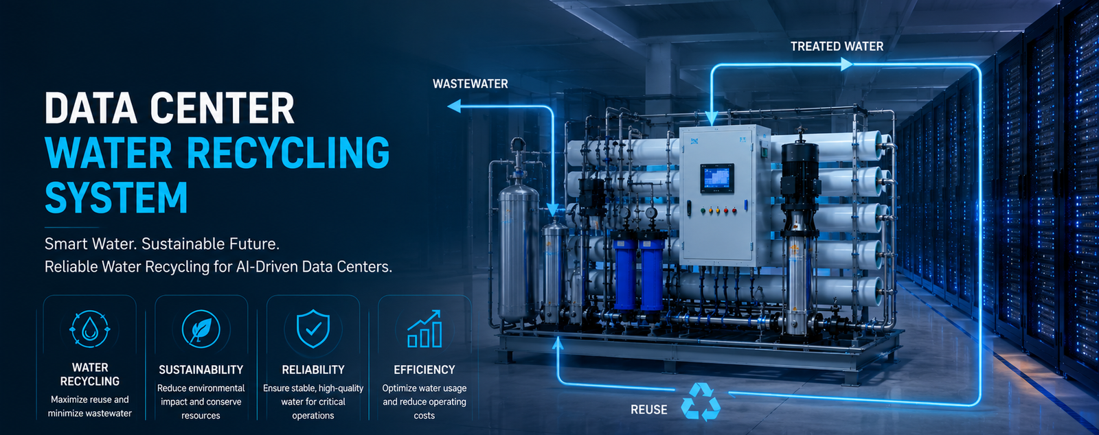
In the context of scaling next-generation high-density AI compute clusters, engineering an automated data center water recycling system is no longer just a sustainability mandate—it is an operational necessity to optimize Water Usage Effectiveness (WUE) and guarantee server uptime. Evaporative cooling infrastructure naturally generates high-TDS (Total Dissolved Solids) cooling tower blowdown (CTBD) as pure water vaporizes. Rather than discharging this mineral-dense wastewater, deploying an on-site closed-loop reclamation network allows facilities to capture, purify, and reuse up to 85% of this stream as premium makeup water, completely shifting facility economics.
To achieve this level of volumetric efficiency while eliminating the risk of scale formation or microchannel clogging, a heavy-duty, multi-stage filtration and purification system must be established.
As a premier supplier of high-end water treatment infrastructure across the United States and Europe, YourWaterGood (www.yourwatergood.com) engineers modular, industrial-grade purification arrays designed to safely process challenging recycled water sources into high-purity process feeds:
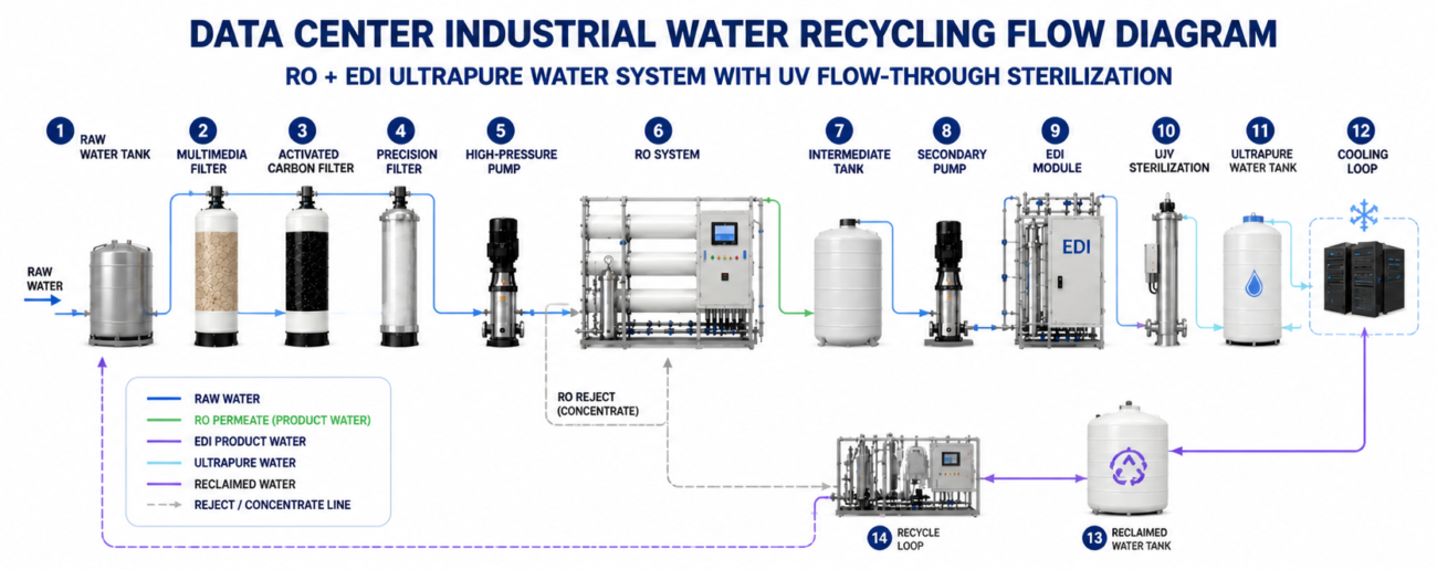
- Multimedia Filtration Array: This initial stage intercepts large-scale physical contaminants, including sediment, rust, and suspended solids from the recycled stream.
- Deep Activated Carbon Beds: Deeply adsorbs residual chlorine and organic compounds, preventing oxidative damage to the sensitive RO membranes downstream.
- Continuous Ion-Exchange Softening: Equipped with a dedicated salt box, this automated system removes calcium and magnesium ions to eliminate scaling, protecting your capital assets from mineral buildup.
- Precision Security Screening: Acts as the final defensive physical barrier to catch any microscopic particulates before the pre-treated stream enters the high-pressure membrane loop.
- High-Rejection Industrial RO Membrane Array: The core desalination stage where high-pressure separation produces high-purity water. Engineered to handle aggressive mineral concentrations, this membrane matrix has demonstrated capacities to reduce raw water TDS from 1300 mg/L down to less than 20 mg/L.
- Continuous Electrodeionization (EDI) Polishing Module: The definitive ultra-pure polishing tier. By passing the RO permeate through a continuous DC electrical field combined with ion-exchange membranes and resin beds, it eliminates residual weakly ionized silica, boron, and trace minerals. This advanced module self-regenerates continuously without requiring any acid-base chemicals, pushing water resistivity up to 10–18.2 MΩ·cm (conductivity <0.1 µS/cm)—perfect for the strict dielectric standards of AI cold plates.
Recycling Is Limited by What Stays Behind, Not What You Reuse
The defining insight behind a data center water recycling system is that evaporative cooling removes water as vapor but leaves every dissolved solid behind. Recycling concentrates those solids with each pass, so the constraint is chemistry, not volume.
Three classes of contaminant accumulate as water is reused:
- Silica — the hardest to remove and the one that polymerizes into unremovable scale, making it the practical ceiling on reuse.
- Hardness (calcium and magnesium) — drives scale on fill, exchangers, and cold-plate microchannels under 100 µm.
- Total dissolved solids (TDS) — raises conductivity and corrosion potential across the loop.
A recycling design that tracks only water volume will balance on paper and fail in chemistry. The recovered water looks abundant, but its contaminant load climbs every cycle until something exceeds its solubility and scales — typically silica, and typically on the most expensive surface in the loop.
The discipline: design the recycling ratio around the limiting contaminant, then provide the treatment and purge to hold it. Volume tells you what is possible; chemistry tells you what is safe.
The Reuse Architecture: Cascading Streams to Minimize Import and Discharge
A recycling system is not a single recovery step — it is a cascade that routes each water stream to a use that tolerates its quality, extracting maximum value before discharge.
The core reuse streams in a data center:
- Cooling tower blowdown — the largest reuse opportunity. Treated with industrial reverse osmosis, the permeate returns to makeup and only the concentrate leaves the loop.
- RO reject (concentrate) — the reject from the high-purity train is too saline for a technology loop but suitable as cooling tower makeup, where it displaces fresh water.
- Cooling-coil condensate — water condensed from air handlers is a recoverable source, though its aggressive low-hardness chemistry requires conditioning before reuse.
- Process and equipment drains — captured and routed back through treatment rather than discharged.
Each stream is matched to a use by quality: ultrapure makeup for the technology loop, moderate-quality water for tower makeup, and the most concentrated reject toward purge or Zero Liquid Discharge (ZLD). The architecture works because a data center has loops at very different purity tiers, and one loop’s reject is another’s acceptable feed.
The engineering rule: cascade by quality, and treat each recycled stream only to the level its next use requires. Over-treating a stream wastes energy; under-treating it contaminates the loop it feeds.
Treating Progressively Worse Water: Why the Train Is Sized for the Concentrate
The pre-treatment in a recycling system cannot be sized for the incoming municipal water, because the water it actually processes is the recycled, concentrated stream — and that changes the entire train.
Municipal makeup is the cleanest water in the system and the easiest case:
- Activated carbon for chlorine and chloramine, and chloride control to protect 316L from pitting corrosion.
Recycled and reclaimed streams are the design basis, and they are far more aggressive:
- High TDS, silica above ~150 ppm, phosphate, ammonia, and organics that intensify with every reuse cycle.
- Requires heavier multimedia filtration, skid-mounted softening, and antiscalant dosing to handle the concentrated load.
- Demands stronger microbiological control, since recycled water carries the nutrients that drive biofilm.
- Pushes membrane selection toward fouling-resistant elements and a recovery rate matched to the concentrate.
A train sized for municipal feed will foul and scale on recycled water within weeks. The recycling system is engineered around its dirtiest internal stream, not its cleanest external one — consistent with ASHRAE TC 9.9 and EPA frameworks.
The Water Balance: Metering Makeup, Reuse, and Purge
A recycling system only holds together if the water balance is measured and controlled. Reuse without metering drifts until contaminants accumulate or a stream runs short.
A controlled water balance tracks four flows:
- Makeup — fresh water imported, the figure a recycling system exists to minimize.
- Reuse — recovered water returned to service, metered by stream.
- Purge / blowdown — the controlled bleed that removes accumulated non-volatiles before they exceed treatable limits.
- Discharge — what leaves the site, capped by EPA / sewer limits.
The purge is the release valve of the whole system. Recycling concentrates contaminants, and without a purge, silica and TDS climb without bound until the loop scales. A larger purge keeps chemistry safe but imports more makeup; a smaller purge saves water but risks scaling. The purge rate is the control point that balances water savings against chemistry, and eliminating it entirely is what forces a move to ZLD.
Metering all four flows into the BMS turns the balance from an assumption into a controlled, reported number — the basis for both WUE reporting and stable operation.
Standard Skids vs Data-Center-Grade Recycling Systems
A commercial skid recovers one stream and ignores the balance. A data-center-grade recycling system cascades multiple streams, treats the concentrate, and controls the water balance for 24/7/365 operation.
| Engineering Parameter | Standard Pre-Engineered Skids | Data Center Grade High-Redundancy Recycling Systems |
|---|---|---|
| Design basis | Incoming feed water | Most concentrated recycled stream |
| Reuse streams | Single recovery step | Blowdown, RO reject, condensate cascade |
| Silica management | Ignored | Designed to the silica ceiling |
| Flow capacity (GPM) | 10–50 GPM | 100–1,000+ GPM, parallel trains |
| Redundancy | Single train | N+1 / N+2 / 2N parallel architecture |
| Purge / ZLD | None | Controlled purge, ZLD readiness |
| Metering | Basic | Full water balance to BMS for WUE |
| Lead time & support | Stock unit, generic spares | Engineered build, documented P&ID, standardized spares |
The design-basis and silica rows decide outcomes: a system sized for incoming feed and blind to silica scales itself as contaminants concentrate, while one designed to the concentrate and the silica ceiling runs indefinitely. The cheaper skid recovers water until it scales, then stops.
To pressure-test a vendor, ask what recycling ratio their design supports and what limits it. A supplier who answers in volume without naming silica has not engineered the chemistry.

Field Engineering Insight: Silica Is the Limiting Reagent That Caps Your Recycling Ratio
Here is the detail that catches teams designing a recycling system on a water-balance spreadsheet: silica, not water volume or TDS, usually sets the maximum recycling ratio — and it does so invisibly until something scales.
When water is recycled through an evaporative system, the water leaves as vapor and the silica stays behind, concentrating with every cycle. Unlike hardness, which softening removes cheaply, silica is expensive to remove and, above roughly 150 ppm, polymerizes into a glassy scale that no acid wash removes once it forms.
So as the recycling ratio climbs, silica climbs toward that ceiling first. A design that targets an aggressive reuse ratio on volume alone discovers that silica caps it far lower — and the discovery often arrives as scale on a cold plate or heat exchanger, which is effectively permanent.
The engineering defense is to treat silica as the controlling design parameter:
- Set the recycling ratio from the silica limit, not the water-balance optimum, so concentrated silica never crosses its solubility.
- Add silica-specific treatment where a higher ratio is required — high-pH RO rejection, lime or lime-soda softening, or a larger controlled purge.
- Monitor silica as a primary parameter, not just conductivity, since conductivity can read acceptable while silica approaches saturation.
- Map the silica ceiling to the assets — once silica scales a cold plate or CDU, the loss is unrecoverable, so the ratio must respect the limit.
This is the kind of detail that never appears on a water-balance summary but decides whether a recycling system runs for years or scales in months. It is also where recycling pays back when done right: a ratio designed to the silica limit cuts makeup and discharge, lowers WUE and OPEX, and keeps cold plates, CDUs, and exchangers scale-free — holding 99.999% uptime while reducing the facility’s water footprint.
Data Center Water Recycling System FAQs
What is a data center water recycling system? A system that recovers and reuses internal water streams — cooling tower blowdown, RO reject, and condensate — to minimize freshwater import and discharge, with treatment sized for the concentrated recycled water rather than the incoming feed.
What limits how much water a data center can recycle? Silica and other non-volatile contaminants concentrate with every reuse cycle. Silica above roughly 150 ppm polymerizes into unremovable scale, so it usually caps the recycling ratio before water volume or TDS does.
How is cooling tower blowdown recycled? Blowdown is treated with industrial reverse osmosis: the permeate returns to makeup, and only the concentrate is purged or routed to ZLD. This is typically the largest single reuse stream.
Can cooling-coil condensate be recycled? Yes. Condensate is a recoverable source, but it is low in hardness and aggressive, so it requires conditioning — remineralization or corrosion inhibitor — before reuse to avoid corroding the loop it feeds.
Does a recycling system reduce WUE? Yes. Reusing internal streams cuts both freshwater withdrawal and discharge, directly lowering Water Usage Effectiveness — increasingly a reported and committed sustainability metric.
How does recycled water differ from municipal water in treatment? Recycled and reclaimed streams carry higher TDS, silica, and organics that intensify each cycle, requiring heavier multimedia, softening, and antiscalant and faster fouling assumptions than municipal feed.
What is the role of a purge in a recycling system? A controlled purge bleeds accumulated non-volatiles — silica and TDS — to keep recycled water within treatable limits. Shrinking the purge saves water but raises scaling risk; eliminating it entirely requires ZLD.
Engineer a Recycling System Around the Limit, Not the Spreadsheet
A data center water recycling system is a chemistry and water-balance decision before it is a volume one. The facilities that recycle successfully are the ones that designed the reuse ratio around the silica ceiling and treated the most concentrated stream — not the ones that balanced on volume and scaled.
Whether you are equipping a single high-density facility or sourcing trains into a larger buildout, YourWaterGood manufactures and ships the equipment factory-direct — a data center water recycling system built on industrial RO for blowdown recovery, EDI, skid-mounted softening, ZLD-ready concentration, and automated dosing, engineered to your water balance.
- Get an Infrastructure Engineering Quote: itemized pricing on 1 t/h–10 t/h recovery and reuse trains sized to your recycling ratio and silica limit.
- Request Technical Data Sheets: recovery rates, reuse-stream specs, and water-balance metering detail for your engineering review.
- Secure B2B Wholesale / Factory-Direct Pricing: source recovery and recycling equipment straight from our manufacturing facility.