
Data Center Water Treatment for High-Density AI GPU Cooling: Engineering the Zero-Failure Loop
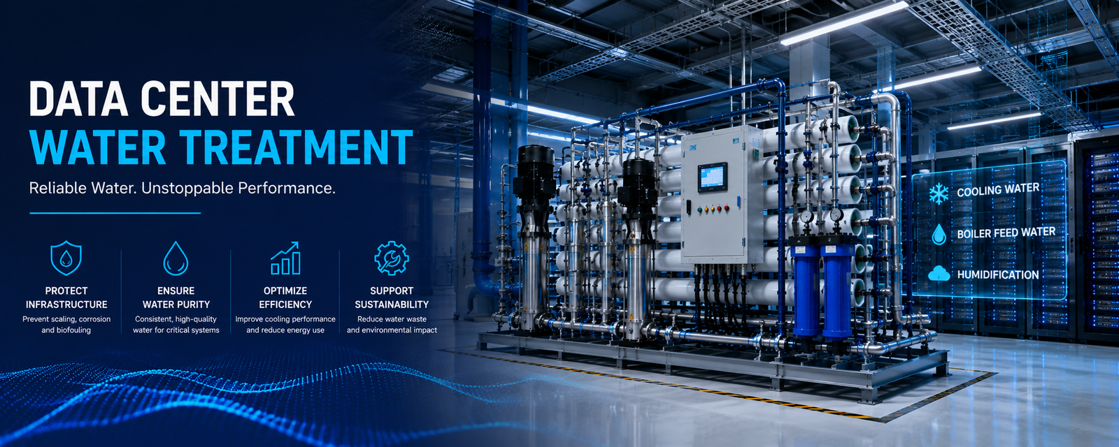
The fastest path to thermal throttling a $40M GPU cluster isn’t a power outage — it’s a cooling loop running at 450 µS/cm conductivity with unchecked silica at 18 ppm.
At rack densities of 40–100 kW and beyond, the thermal margin between full-performance operation and irreversible GPU junction damage compresses to single-digit degrees Celsius. Air cooling is already a non-starter above ~25 kW per rack. What takes its place — direct-to-chip cold plate liquid cooling, rear-door heat exchangers, and cooling tower-fed chilled water plants — lives or dies on water chemistry control.
In next-generation high-density AI compute clusters, continuous thermal management is no longer a generic facility utility—it is a mission-critical variable directly governing system uptime and Water Usage Effectiveness (WUE). Modern hyperscale infrastructure splits hydronic architecture into two distinct ecosystems: the Facility Cooling System (FCS) for open or closed evaporative loops, and the Technology Cooling System (TCS) for direct-to-chip (DTC) liquid cooling cold plates. Implementing a rigorous data center water treatment strategy is indispensable to counteract the catastrophic risks of mineral scaling, under-deposit pitting corrosion, and microbiological biofouling across these complex metallic networks.
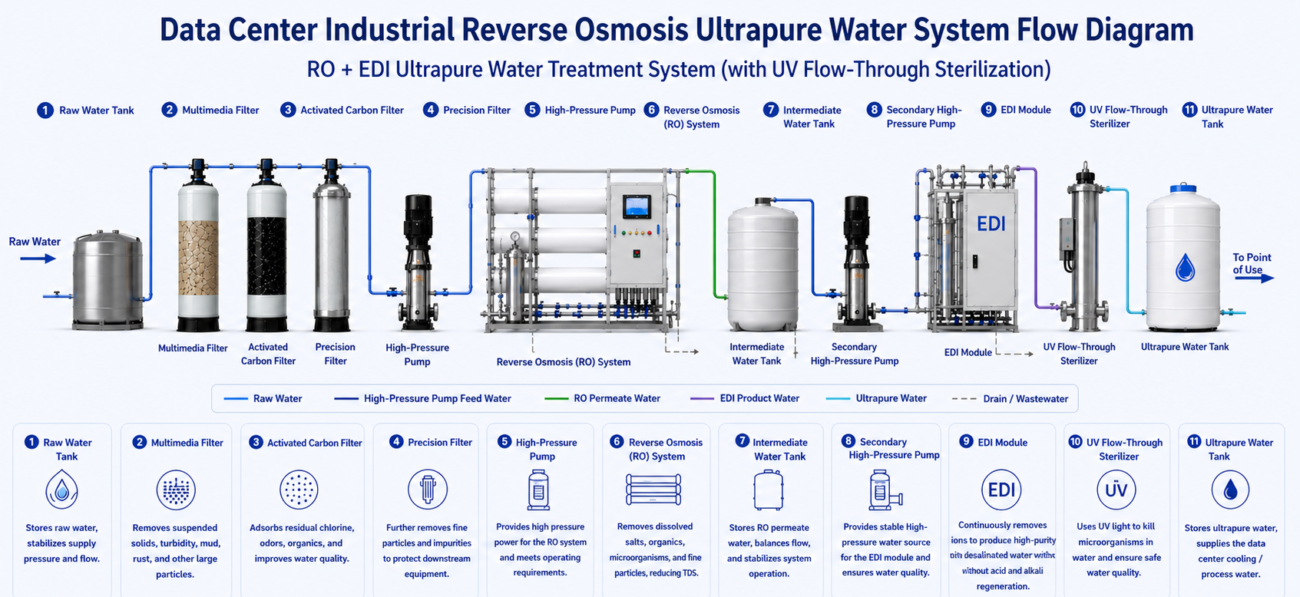
For high-density chip cooling environments that demand exceptionally low conductivity, standard filtration is insufficient. YourWaterGood, a premier global industrial water purification provider, engineers a fully integrated, automated multi-stage framework designed to optimize water chemistry and unlock higher Cycles of Concentration (CoC) safely:
- Multimedia Mechanical Stack: Intercepts large-scale physical particulates, silt, and macro-suspended solids to drop the Silt Density Index (SDI) ahead of membrane stages.
- Deep-Bed Activated Carbon Adsorption: Adsorbs residual chlorine, volatile organic compounds (VOCs), and aggressive oxidants, protecting sensitive downstream elements from irreversible chemical degradation.
- Automated Ion-Exchange Softening: Utilizes dedicated brine-tank regeneration sequences to remove calcium and magnesium ions, entirely eliminating hard water scale formation on heat exchange surfaces.
- Precision Security Micro-Filtration: Serves as a defensive physical barrier catching microscopic particles to shield high-pressure equipment.
- High-Rejection Industrial RO Array: Operates under optimized hydraulic pressure (>0.2 MPA inlet pressure) to separate total dissolved solids (TDS), heavy metals, and silica down to 0.0001 microns. In documented infrastructure layouts, this stage reduces raw water TDS from 1300 mg/L to less than 20 mg/L.
- Continuous Electrodeionization (EDI) Module: The ultimate ultra-pure polishing phase. By combining ion-exchange membranes and resin beds under a continuous DC electric field, it removes residual weakly ionized silica and trace minerals without requiring acid-base chemical regeneration. This module drives product water resistivity up to 10–18.2 MΩ·cm (conductivity <0.1 µS/cm), matching the strictest dielectric standards of AI cold plate microchannels.
Fast Check Product: https://yourwatergood.com/product/industrial-reverse-osmosis-system/
Why Micro-Channel Cold Plates Fail Long Before Their Design Life
The microchannel architecture that makes modern GPU cold plates thermally effective — internal channels narrower than 100 µm — is exactly what makes them catastrophically intolerant of water quality drift.
A single scaling event driven by calcium carbonate or silica precipitation at operating temperatures of 35–55°C can bridge a 75 µm channel in fewer than 90 days at 3× cycles of concentration. Once blocked, flow restriction increases differential pressure (ΔP) across the cold plate, reducing GPU-junction-to-coolant thermal conductance. The GPU’s embedded diode temperature sensor reports a rise; the system throttles clock frequencies; compute throughput drops 15–30% before any operator alarm fires.
Field Engineering Insight: The failure mode most operators miss is temperature-driven reverse osmosis membrane flux decline. At inlet water temperatures below 15°C (common in Phoenix, AZ winter months or Ashburn, VA shoulder seasons), RO permeate flow can drop 25–35% due to viscosity-driven flux reduction — a factor quantified by the Temperature Correction Factor (TCF). An undersized RO skid designed for summer conditions will go into water deficit precisely during cold commissioning windows, forcing operators to add insufficiently treated makeup water directly into the TCS. This is the upstream root cause of early cold plate fouling on many newly commissioned AI clusters.
Cooling Tower COC Engineering: The Leverage Point for WUE Reduction
Hyperscale operators in water-stressed markets — Maricopa County (Phoenix), Northern Virginia, and Central Texas — face escalating municipal water restrictions tied to Water Usage Effectiveness (WUE) covenants in their permits.
Cooling tower cycles of concentration (COC) is the highest-leverage operational variable available. Increasing COC from 3 to 6 cuts makeup water consumption by approximately 20% and blowdown volume by 50% — quantified by DOE and independently validated by treatment operators. Achieving 6+ COC sustainably, however, demands a fully engineered chemical program:
- Automated conductivity-based blowdown control: Continuous inline sensors with ±2% accuracy, directly integrated into BMS/DCIM
- Scale inhibitor dosing: Phosphonate-based or polymer-based dispersants dosed proportional to makeup flow via automated chemical metering pumps
- Biocide rotation program: Alternating oxidizing (sodium hypochlorite) and non-oxidizing biocides on a 7–14 day cycle to prevent Legionella and biofilm colonization — a direct regulatory obligation under EPA and state cooling tower registration frameworks
- Anti-silica scale chemistry: Silicon dioxide solubility drops sharply above 180 ppm in concentrate; at COC 6–8 with typical Southwest US municipal supply (raw silica 20–30 ppm), silica in circulating water can reach 120–180+ ppm without suppression chemistryReady to right-size your cooling tower chemical treatment and blowdown RO recovery system? Request a Data Center Water Sizing Consultation →
Municipal Tap vs. Reclaimed Water: Two Entirely Different Pretreatment Architectures
Many facilities engineering teams make the critical error of specifying a single pretreatment train for both source water types. Phoenix-area data centers frequently use Class A+ reclaimed water as cooling tower makeup — a water source with TDS ranging 500–1,200 ppm, elevated ammonia, and biological oxygen demand (BOD) that municipal potable water never carries.
| Parameter | Municipal Potable Feed | Reclaimed/Recycled Water Feed |
|---|---|---|
| Typical TDS (ppm) | 150–400 | 500–1,200 |
| Silica risk | Moderate | High (elevated SiO₂, often 30–50 ppm) |
| Chloramine/chloride corrosion risk | High (residual Cl₂ / chloramine attacks RO membranes) | Moderate to high (Cl⁻ 100–300 ppm) |
| Biological loading | Low (post-disinfection) | Moderate to high (BOD, nutrients present) |
| Pretreatment requirement | Carbon media + softening + RO | Coagulation + media filtration + UF + RO + EDI + UV |
| RO design recovery target | 75–82% | 65–75% (due to higher fouling index, SDI) |
Specifying a reclaimed water RO skid at the same recovery rate as a potable water system is a design error that will collapse membrane life to under 18 months and void most OEM warranties.
The True CAPEX/OPEX Case for Data Center-Grade Water Systems
The financial argument for high-specification water treatment isn’t about chemical spend — it’s about protecting the critical assets sitting downstream.
OPEX reduction:
- Each manual heat exchanger descaling event in a production CDU loop requires a 4–8 hour partial shutdown window, often requiring N+1 failover activation — at an estimated cost of $15,000–$40,000 per event including labor, chemical flushing, and downtime opportunity cost
- Side-stream filtration and automated softening eliminate the primary condition that forces emergency descaling cycles
- Cooling tower fill replacement due to biological fouling averages $80,000–$250,000 per tower at hyperscale scale; automated biocide dosing extends fill life by 3–5×
Capital asset lifespan:
- Cold plates (NVIDIA GB200 direct liquid cooling platforms): Replacement cost per chassis runs $8,000–$25,000 per node; premature failure from micropassage blockage is 100% preventable with correct TCS water quality
- CDUs and high-pressure pumps: Corrosive pitting from chloride or low-pH excursions on stainless/copper components generates particulate that then re-enters the loop — a cascade failure mechanism
- RO membranes: Properly conditioned feed water extends spiral-wound membrane life from a degraded 18–24 months to the design-rated 4–7 years
Uptime assurance:
ASHRAE TC 9.9 H1-class systems (AI/HPC, recommended 18–22°C inlet range) operate with the tightest thermal margins of any data center equipment class. A localized hot spot of +3–5°C above the H1 upper limit triggers automatic frequency scaling on NVIDIA H100/B200 and AMD MI300X platforms — directly reducing delivered FLOP/s capacity per rack-hour sold to cloud tenants.
Standard Industrial Skids vs. Data Center-Grade Systems: The Specification Gap
This is where most procurement teams discover the real risk: an industrial water treatment skid rated for manufacturing or pharmaceutical use does not meet data center N+1 uptime and BMS integration requirements.
| Specification Dimension | Standard Industrial Skid | Data Center-Grade High-Redundancy System |
|---|---|---|
| Flow range (GPM) | Fixed-rate, manual trim valves | Variable 10–500 GPM, VFD-controlled, pressure-independent |
| Redundancy architecture | Single train (N) | N+1 or 2N dual-train with auto-failover in < 30 seconds |
| BMS/DCIM integration | Analog gauges, local HMI only | Modbus TCP/IP, BACnet, SNMP; live conductivity/pH/flow to DCIM |
| Conductivity alarm | Manual sampling, weekly | Continuous inline ±1% accuracy sensors, auto-blowdown trigger + DCIM alert |
| Filtration precision | 5–25 µm nominal | 1–5 µm absolute (pre-CDU), with 0.2 µm polishing option for EDI loops |
| Delivery & commissioning | 16–26 weeks (custom engineering) | 8–14 weeks (pre-engineered skid with site adaptation) |
| Compliance documentation | Basic O&M manual | ASHRAE TC 9.9, EPA blowdown registration, IFC data package, FAT/SAT protocols |
Selecting the Right Technology Train for Your Facility Water Architecture
The correct product selection depends on three inputs: source water TDS, closed-loop target resistivity, and cooling tower target COC.
For cooling tower makeup and high-COC operation (Facilities Water System — FWS):
- Industrial Reverse Osmosis Systems producing 20–500 GPD to 500+ GPM, configured with anti-scalant pre-dosing and automated membrane cleaning (CIP) sequences
- Skid-mounted softeners with duplex/triplex configurations for N+1 ion exchange capacity, sized to handle the hardness load at target COC without resin exhaustion events
For closed-loop Technology Cooling System (TCS) — direct-to-chip liquid cooling:
- EDI (Electrodeionization) continuous deionization trains producing permeate resistivity > 10 MΩ·cm (conductivity < 0.1 µS/cm), eliminating the chemical regeneration cycle and chemical storage hazard that traditional mixed-bed DI creates
- Automated chemical dosing systems for pH stabilization, corrosion inhibitor management, and biocide injection with flow-paced metering precision of ±1%
For blowdown recovery and Zero Liquid Discharge (ZLD) compliance:
- High-recovery second-pass RO brine concentration systems designed to push cooling tower blowdown to 85–90% recovery before disposal — critical in Ashburn, VA (Loudoun County water use covenants) and Phoenix metro markets with active blowdown volume restrictions
The entire product architecture described above is available as factory-direct, pre-engineered skid packages through the data center water treatment, configured specifically for data center water chemistry profiles.
ASHRAE TC 9.9 and EPA Compliance: The Non-Negotiables
ASHRAE TC 9.9’s 2024 liquid cooling white paper explicitly requires monitoring of coolant quality and filtration as an operational mandate — not a recommendation — for any facility deploying water-cooled servers. Failure to document a formal water quality management program creates direct liability exposure in the event of a cooling-related hardware loss event.
On the regulatory side:
- EPA NPDES permit requirements apply to cooling tower blowdown discharge exceeding threshold volumes into municipal storm systems; most hyperscale facilities exceed these thresholds within 90 days of full load
- Legionella water management plans (per ASHRAE 188 and CDC Model Aquatic Health Code) are legally required in most states for any cooling tower above a defined basin volume — the chemical treatment program must document compliance against these plans
A water treatment vendor that cannot provide an ASHRAE TC 9.9-compliant water quality management documentation package as a standard deliverable is not an appropriate vendor for mission-critical data center infrastructure.
Frequently Asked Questions
Q1: What conductivity target should the closed-loop cooling water in a direct-to-chip liquid cooling system maintain?
Conductivity should be maintained at ≤ 10 µS/cm continuously, measured at the CDU inlet at 20–25°C. Alarm setpoint should be configured at 15 µS/cm with automated makeup water dosing or blowdown initiated; IBM, NVIDIA, and AMD all publish ≤ 10 µS/cm as the maximum allowable threshold in their liquid cooling technical specifications.
Q2: What is the recommended silica limit for data center cold plate liquid cooling loops, and why does it matter?
Silica (SiO₂) should be maintained at ≤ 1.0 ppm in the TCS closed loop. At operating temperatures above 40°C and flow velocities that create localized concentration gradients inside micro-channel passages (< 100 µm), amorphous silica deposits form irreversibly. Unlike calcium carbonate scale, silica scale cannot be dissolved by acid cleaning without risking membrane and elastomer damage in the loop.
Q3: How do cycles of concentration (COC) impact WUE in a data center cooling tower?
Increasing COC from 3 to 6 reduces makeup water consumption by approximately 20% and cuts blowdown volume by 50%. For a 50 MW data center consuming 3,000–5,000 GPM of cooling tower makeup, this translates to a reduction of 600–1,000 GPM in average water draw — directly improving WUE from ~1.8 L/kWh toward 1.1–1.3 L/kWh at full load.
Q4: What is the difference between EDI and traditional mixed-bed deionization for data center TCS makeup water?
EDI (Electrodeionization) is a continuous, chemical-free process producing > 10 MΩ·cm resistivity water without batch acid/caustic regeneration cycles. Mixed-bed DI delivers equivalent purity but requires scheduled chemical regeneration, creating shutdown windows and chemical storage requirements incompatible with 99.999% uptime architectures. For N+1 or 2N TCS makeup systems, EDI is the only operationally viable technology.
Q5: Does reclaimed/recycled water require a different RO pretreatment configuration than municipal potable water?
Yes — extensively different. Reclaimed water typically carries TDS of 500–1,200 ppm, elevated BOD, and silica concentrations of 30–50 ppm. Required pretreatment adds coagulation, multimedia filtration, ultrafiltration (UF), and UV disinfection ahead of the RO membrane array. Design recovery rates must be reduced to 65–75% versus 75–82% for potable feeds to avoid exceeding the silica or salt concentration polarization limits at the concentrate side of the membrane.
Q6: What redundancy level is required for data center water treatment systems supporting Tier III or Tier IV facilities?
Tier III (N+1 concurrently maintainable) facilities require full N+1 redundancy across all water treatment trains — including softeners, RO pressure vessels, chemical dosing pumps, and inline instrumentation. Tier IV (2N fault tolerant) requires fully independent dual-path water treatment with automatic failover in < 30 seconds and zero shared single points of failure. All switchover events must be logged to the DCIM/BMS system with timestamp and alarm acknowledgment.
Q7: What are the most common water quality failure modes that lead to GPU thermal throttling in liquid-cooled AI clusters?
Three mechanisms dominate field incident reports: (1) Cold plate micro-channel silica or calcium scale blockage, increasing ΔP and reducing per-chip coolant flow below design GPM; (2) Biofilm colonization in CDU manifolds, which increases hydraulic resistance and insulates heat transfer surfaces, raising coolant return temperatures by 3–8°C; and (3) Chloride-driven pitting corrosion releasing copper particulate that migrates downstream, triggering 25–50 µm strainer blockage events that reduce rack-level flow rates without a visible system alarm.
Get Your Data Center Water System Engineered to Mission-Critical Spec
Your cooling infrastructure is only as reliable as the water running through it. A GPU cluster operating at 80 kW per rack with compromised TCS water chemistry isn’t a 99.999% uptime asset — it’s a scheduled incident waiting for a trigger.
yourwatergood.com provides factory-direct, data center-configured water treatment systems — from high-recovery Industrial RO skids and EDI ultrapure systems to automated cooling tower chemical dosing and blowdown recovery trains — engineered specifically for AI data center, HPC, and hyperscale colocation facilities.
Take the next step:
- Request a Custom Data Center Water Sizing Consultation — submit your source water TDS, GPM requirements, and COC targets for a facility-specific engineering proposal
- Request B2B / Factory-Direct Wholesale Pricing — volume pricing for multi-site hyperscale deployments, EPC contractors, and data center REIT operators