
Custom Reverse Osmosis System for Cooling Water: Optimizing High-Density AI Data Center PUE
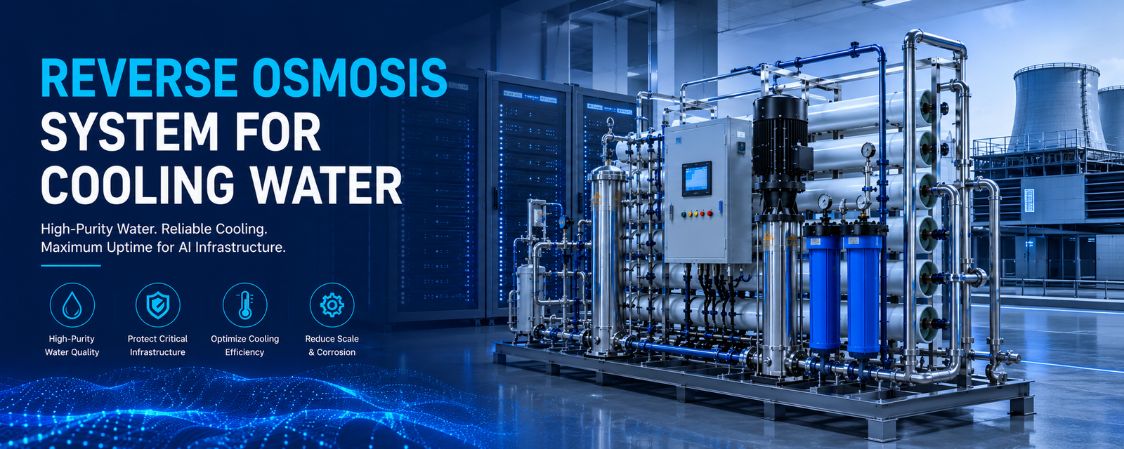
High-density AI compute clusters drawing 40 kW to 100 kW+ per rack have broken traditional fan-based heat rejection limits. Modern infrastructure forces facility engineers to redesign the hydronic loops powering hyper-scale deployments. For both direct direct-to-chip liquid cooling and evaporative cooling towers, raw water chemistry fluctuations represent a major source of thermal inefficiency and asset degradation risk. Uncontrolled mineral scaling, micro-particulate deposits, and biological film accumulation increase heat-transfer resistance, causing localized GPU thermal throttling and risking catastrophic server chassis leaks. Deploying a custom engineered reverse osmosis system for cooling water stabilizes thermal conductance, lowers Water Usage Effectiveness (WUE), and guarantees mission-critical reliability.
Next-generation AI computing clusters operate at unprecedented heat densities, making traditional air-cooling loops insufficient. Liquid cooling architectures utilize server cold plates containing microchannels narrower than 100 microns. Standard raw source water contains dissolved silica, calcium, and magnesium ions that rapidly form highly insulative mineral scale barriers under extreme thermal loads. Deploying a dedicated industrial reverse osmosis system for cooling water—such as the double-pass RO and EDI plants engineered by YourWaterGood—is required to continuously strip 99% of dissolved ions and maintain loop TDS below 10 mg/L, preventing chip-level thermal throttling and unexpected cluster shutdowns.
Evaporative cooling systems and cooling towers must continuously purge concentrated mineral streams via water blowdown to avoid massive scale fouling, which dramatically increases fresh water consumption and degrades a facility’s WUE score. By routing makeup water or cooling tower blowdown through a double-pass industrial reverse osmosis system paired with a continuous electrodeionization (EDI) stack, the plant removes scaling precursors without chemical regeneration downtime. This ultra-low conductivity permeate allows the facility to safely run at significantly higher Cycles of Concentration (CoC), decreasing overall freshwater intake demands by up to 40%.
To guarantee constant water flux and prevent premature membrane blinding, the on-site physical infrastructure must ensure a reliable inlet supply pressure baseline of greater than 0.2 MPa. If local utility pressures fluctuate, variable-frequency booster pumps must be integrated before the precision filters. Furthermore, the system’s concentrated water discharge line layout must remain completely unobstructed and free of any throttling valves to prevent concentration polarization from scaling the membrane surfaces. Finally, the layout must incorporate intermediate and pure water storage tank configurations to effectively buffer peak demand spikes across the Technic Cooling System (TCS) loop.
Fast Check Product: https://yourwatergood.com/product/industrial-reverse-osmosis-system/
To maintain a continuous 24 hour uptime profile, infrastructure procurement mains must mandate strict, quantified engineering criteria from filtration partners:
- Dissolved Silica Controls: Preventing irreversible amorphous silica scale formations inside high-flux micro-channels by maintaining saturation levels below precipitation thresholds.
- 99.999% Continuous Availability: Executing parallel, multi-train hydraulic configurations to support un-interrupted water processing during automated media maintenance cycles.
- Real-Time Telemetry Integration: Embedding online conductivity monitoring arrays with automatic dump-valve overrides to handle incoming raw water quality spikes.
- Advanced Anti-Scalant Dosing Integration: Maximizing hydraulic recovery rates while protecting secondary heat exchangers from chemical carrier fouling.
| Engineering Parameter | Data Center Site Vulnerability | YourWaterGood Equipment Configuration | Operational Performance Metric |
| System Volumetric Capacity | Fluctuating multi-megawatt room scaling requirements | Pre-assembled, modular containerized system arrays | 1 t/h to 10 t/h continuous stable permeate flux |
| Pre-Treatment Safeguards | Particle-induced membrane fouling and blinding | Quartz sand, activated carbon, and automated softener nodes | Eliminates macro-sediments; protects downstream membrane elements |
| Desalination Core Performance | Mineral deposit buildup on cooling surfaces | Dual-pass high-rejection RO membrane configurations | Compresses high raw water TDS down to < 10 mg/L |
| Ultrapure Deionization Fluid Polishing | Microchannel localized pitting & electrical tracking | Continuous Electrodeionization (EDI) stack module | Zero chemical regeneration downtime; delivers up to 18.2 MΩ·cm |
| Hydraulic Equilibrium Baseline | Local municipal grid feed line pressure drops | Integrated high-pressure booster pump stations and VFD controls | Maintains nominal continuous throughput at inlet water pressure > 0.2 MPa |
| Smart Process Automation | Manual maintenance overhead & unexpected outages | PLC smart-logic controller with digital pressure gauges and flow meters | Automated backwash flushing; slashes localized manual operational costs by 30% |
| Brine Management Alignment | Concentration polarization & sudden membrane scale crystallization | Open, unrestricted concentrated water discharge line configurations | Valve-free brine layout prevents instant membrane scaling under high recovery |
Thermodynamic Realities of High-Density GPU Racks and Micro-Channel Clogging Risks
Direct-to-chip liquid cooling configurations depend on coolant fluid passing through internal micro-channels with clearances under 100 microns. At this microscopic scale, the localized heat flux at the silicon-copper interface is intensely concentrated. Any presence of residual hardness or dissolved silica in the cooling loops triggers rapid, localized mineral precipitation.
Unlike soft calcium carbonate scale, which can be dissolved via acidic cleaning processes, silica forms an exceptionally dense thermal insulation barrier. This barrier increases thermal resistance across the cold plate, leading to sudden junction temperature spikes and automated GPU throttling.
Furthermore, data centers deploying recycled or reclaimed municipal water face elevated risks from high chloride and sulfate concentrations. These ions elevate the fluid’s galvanic potential, attacking specialized brazed joints within Cold Plate Units (CDUs). Utilizing primary membrane desalination prevents these corrosive elements from ever reaching the critical computing environment.
Maximizing Cooling Tower Cycles of Concentration via Advanced Desalination
Evaporative cooling towers reject enormous thermal loads by turning water into vapor, a process that naturally concentrates remaining dissolved solids. If the makeup loop relies on unrefined municipal water, the tower must be frequently blown down to avoid scaling. This process wastes millions of gallons of water annually and degrades the facility’s Water Usage Effectiveness (WUE) metrics.
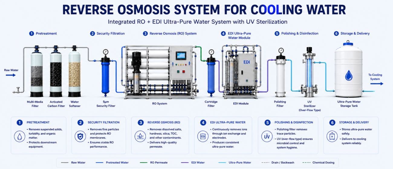
Integrating a multi-stage filtration framework minimizes blowdown frequency by stripping scaling precursors from the feed loop. yourwatergoodcompany implements a reliable five-stage engineering layout to process challenging source water into high-purity process water:
1. Multimedia Filtration Stack
This primary stage intercepts large-scale physical contaminants, including sediment, rust, and suspended solids down to 20 microns. This prevents downstream valve erosion and protects secondary filtration media.
2. Deep-Bed Activated Carbon Adsorption
This phase deeply adsorbs residual chlorine, chloramines, and dissolved organic compounds. Stripping oxidizing agents is vital to prevent oxidative damage to the thin-film composite membranes downstream.
3. Continuous Ion-Exchange Softening
Equipped with an automated brine regeneration system, this phase removes calcium and magnesium ions to eliminate scaling. This chemical exchange systematically protects downstream thermal equipment from mineral buildup.
4. Precision Security Filtration Barrier
This stage acts as the final defensive physical barrier to catch any microscopic particulates or escaping resin fines before the fluid enters the high-pressure pumping stage.
5. High-Rejection Reverse Osmosis Array
The core desalination stage where high-pressure separation produces high-purity water. This configuration reduces raw water Total Dissolved Solids (TDS) from 1300 mg/L to less than 20 mg/L, dropping conductivity down to manageable levels.
[Raw Influent Stream]
│
▼
[Multimedia Pre-Filter] ──► Intercepts macro-sediment & suspended solids
│
▼
[Activated Carbon Bed] ──► Adsorbs free chlorine to protect membranes
│
▼
[Ion-Exchange Softener] ──► Swaps Calcium/Magnesium for non-scaling Sodium
│
▼
[Security Micro-Filter] ──► Traps microscopic particulates & resin fines
│
▼
[High-Pressure RO Arrays]──► Strips TDS from 1300 mg/L to under 20 mg/L
Mitigating Reclaimed Water Risks and Municipal Chloride Corrosion
As environmental regulations tighten across key clusters like Ashburn, Virginia, and Phoenix, Arizona, data centers are forced to utilize recycled or reclaimed municipal wastewater. While cost-effective, reclaimed water carries highly unpredictable water quality profiles. It frequently exhibits elevated ammonia, phosphate, and organic matter levels, which can accelerate biological fouling within open-loop cooling towers.
Biological film behaves as an insulating slime layer that has a thermal conductivity lower than mineral scale. It also fosters microbially induced corrosion (MIC), which can breach stainless steel heat exchangers.
To safely leverage reclaimed water streams, our system designs combine robust automated biocide dosing with high-rejection reverse osmosis. This arrangement strips organic nitrogen and phosphate compounds from the water supply, starving bacteria of the nutrients required to colonize cooling tower surfaces and ensuring regulatory compliance with local EPA frameworks.
[Request a Data Center Water Sizing Consultation]
Thermal Flux Management and Temperature Correction Factor Corrections in Winter Operations
A common failure point in critical infrastructure sizing is failing to account for the Temperature Correction Factor (TCF) of reverse osmosis membranes. Water viscosity increases as temperatures drop. When source water temperatures plunge during winter months, the physical flux through a standard membrane decreases by roughly 3% per degree Celsius.
If high-pressure booster pumps are not sized to compensate for this increased fluid resistance, net permeate output drops. This leaves the facility vulnerable if a sudden computing workload surge demands high cooling tower evaporation rates during cold weather.
To eliminate this operational vulnerability, yourwatergoodcompany utilizes industrial-grade variable-frequency drive (VFD) booster pumps engineered to maintain stable inlet operating pressures exceeding 0.2 MPa. These systems operate with real-time PSI differential gauges to provide instant feedback, allowing facility managers to track flux dynamics and execute predictive maintenance protocols long before thermal downtime occurs.
Continuous Electrodeionization (EDI) vs. Mixed Bed Polishers for Ultrapure Loops
Secondary liquid loops that circulate coolant directly across server internal components require ultrapure water with extremely low conductivity (≤ 0.1 μS/cm). While traditional mixed-bed deionization tanks can hit these targets, they require periodic offline chemical regeneration using hazardous acids and alkalis, adding logistical complexity to data center sites.
Continuous Electrodeionization (EDI) modules solve this issue by combining ion-exchange resins, ion-selective membranes, and an applied DC electrical field. This process splits water molecules into hydrogen and hydroxyl ions, continuously regenerating the internal resin bed inline without requiring chemical interventions.
Integrating an EDI module into the filtration loop delivers distinct operational benefits:
- Stable Permeate Resistance: EDI produces a reliable, continuous stream of high-purity water without the water quality dips associated with exhausted mixed-bed resin tanks.
- Footprint Optimization: The compact, modular design minimizes physical space requirements inside the central utility plant, allowing for flexible scaling as server halls expand.
- Elimination of Chemical Footprints: Because regeneration occurs electrically, the system produces no hazardous wastewater effluents, simplifying facility compliance with local environmental discharge regulations.
Engineering Redundancy: Mission-Critical Systems vs. Standard Skids
Data center utility plants cannot tolerate single points of failure. Standard commercial water treatment systems lack the component grade, material thickness, and structural backup systems required to support continuous hyper-scale computing loads.
| Engineering Parameter | Standard Pre-Engineered Skids | Data Center Grade High-Redundancy Systems |
| Hydraulic Flow Capacity | Fixed 5 to 20 GPM | Scalable 1 t/h to 10 t/h+ per train |
| Redundancy Configuration | Single Train (0% Redundancy) | N+1 or 2N Duplex/Triplex Parallel Architecture |
| Piping & Housing Materials | Thin-walled PVC / Plastic | Thickened stainless steel or high-grade UPVC |
| BMS Protocol Integration | Localized LCD Only | Native Modbus RTU / BACnet IP for SCADA telemetry |
| Automated Maintenance | Manual Backwash Valves | Pneumatic/Electric Actuated Automatic Flushing Cycles |
| Filtration Element Precision | 5.0 to 10.0 microns | Down to 0.0001 microns via multi-stage arrays |
Technical FAQs for Data Center Infrastructure Managers
How does water treatment directly reduce infrastructure OPEX?
Mineral scaling as thin as 0.5 mm inside cooling tower heat exchangers increases thermal resistance by over 20%. This forces chiller compressors to consume significantly more energy to satisfy cooling demands, degrading Power Usage Effectiveness (PUE). Purified water reduces mechanical cleaning frequencies, lowers chemical scaling inhibitor expenses, and minimizes cooling tower blowdown waste.
What are the standard water quality guidelines for direct-to-chip liquid cooling?
Per ASHRAE TC 9.9 guidelines, water circulating through secondary cooling loops and direct cold plates must maintain water conductivity below 5 uS/cm, total hardness below 1.0 ppm as CaCO₃, and dissolved silica below 1.0 ppm to completely eliminate micro-channel fouling and galvanic corrosion risks.
How do your systems manage high-silica source water without blinding membranes?
We integrate specialized chemical anti-scalant dosing loops upstream of our reverse osmosis arrays. These anti-scalants modify the crystalline matrix of dissolved silica and calcium salts, keeping them in suspension even past their normal saturation limits so they can exit via the concentrated wastewater stream without blinding the membranes.
Can EDI technology completely eliminate mixed-bed ion exchange tanks?
Yes. For mission-critical data center loops, EDI is the preferred choice because it operates continuously without requiring shutdowns for acid/base chemical regeneration, lowering total cost of ownership (TCO) and removing hazardous chemical footprints from the facility site.
What inlet pressure conditions are required for large-scale RO configurations?
Our industrial filtration arrays require a stable minimum inlet pressure of 0.2 MPa. For facility sites with lower municipal supply pressures, we integrate dedicated pre-boost pump skids with variable frequency drives to ensure constant, non-surging hydraulic feed rates.
Secure Your High-Density Cooling Infrastructure
Thermal management failures in next-generation AI compute clusters can cause costly hardware damage and operational downtime. Protecting high-density CDUs, cold plates, and cooling towers requires a high-rejection reverse osmosis system for cooling water from a water purification partner that understands critical infrastructure engineering.
Contact our application engineering team today to receive:
- A comprehensive, site-specific data center water sizing and layout consultation.
- Direct B2B factory pricing on fully customized, skid-mounted industrial purification systems.
[Request a Data Center Water Sizing Consultation]