
Industrial Water Treatment for AI Data Centers: System Design & N+1 Redundancy Engineering

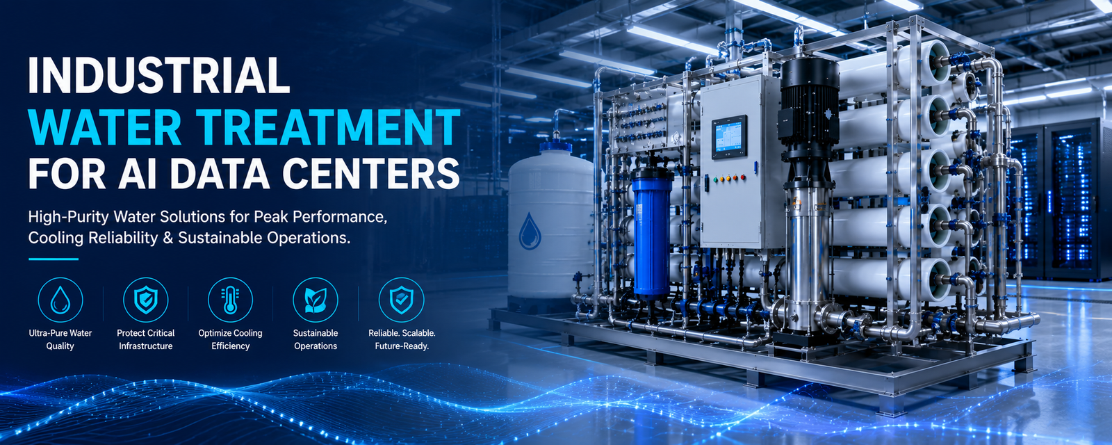
Industrial water treatment for AI data centers is not a single-skid problem. It is an integrated system architecture challenge that must simultaneously manage three distinct water streams—municipal potable feed, reclaimed/recycled water, and facility process returns—each carrying completely different contamination profiles and scaling risks.
At rack densities of 40–100 kW+ per unit, the failure of any single water treatment component cascades immediately into GPU thermal throttling, compressor energy spikes, or unplanned cooling system shutdown. A single day of downtime in a 50 MW hyperscale facility costs $500K–$2M in lost compute revenue. Water treatment system design is not a capex optimization exercise—it is a mission-critical uptime variable that demands N+1 or 2N redundancy, real-time BMS integration, and zero single points of failure.
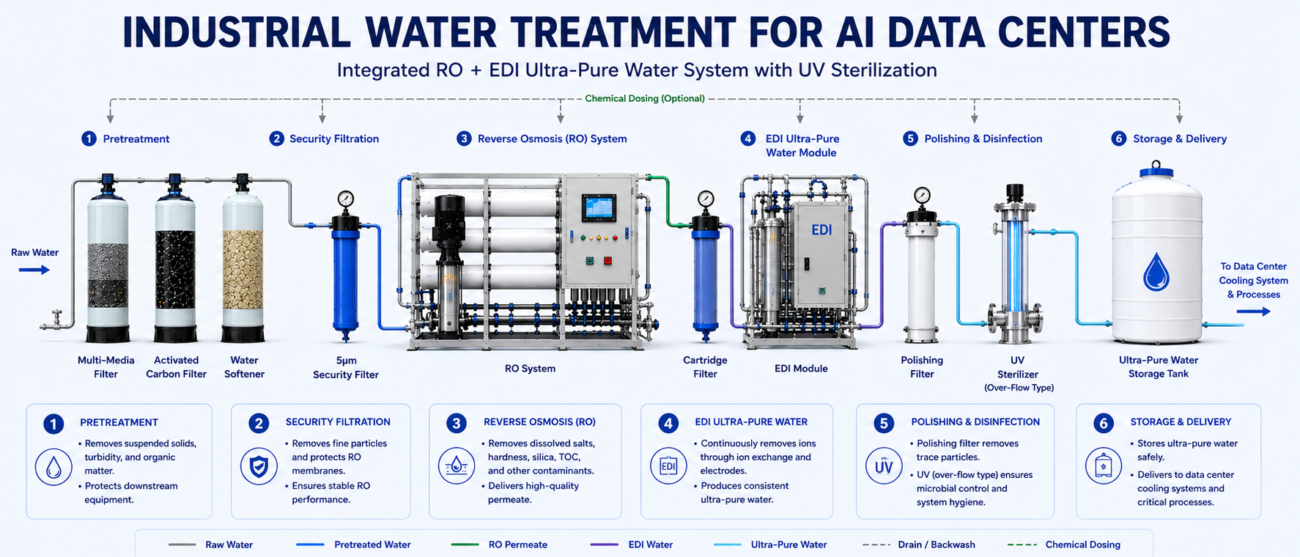
High-density AI computing infrastructure requires direct-to-chip liquid loops because legacy air cooling cannot handle the severe thermal gradients. Server cold plates feature internal fluid microchannels under 100 microns. Standard source water contains suspended solids and hardness minerals that form highly insulative scale barriers under extreme heat fluxes.Implementing a multi-stage industrial water treatment system—like the 5-stage RO and EDI systems from YourWaterGood—is required to drop TDS to under 10 mg/L and remove scale-forming ions
, keeping cooling lines completely clear to prevent hardware thermal throttling.
High mineral concentrations force data center cooling towers to continuously perform water blowdowns to avoid scaling, which severely degrades Water Usage Effectiveness (WUE).Utilizing a double-pass RO system and an EDI polishing stack from YourWaterGood removes 99% of dissolved solids and weak ions without relying on traditional mixed-bed chemical regeneration shutdowns. This chemical-free continuous operation stabilizes loop resistivity at 18.2 MΩ·cm, prevents galvanic pitting, and allows the cooling loops to operate at higher Cycles of Concentration (CoC)—saving up to 40% on fresh makeup water demands.
Fast Check Product: https://yourwatergood.com/product/industrial-reverse-osmosis-system/
Critical System-Level Engineering Non-Negotiables:
- Separate treatment trains for TCS (Technology Cooling System) and FCS (Facility Cooling System): Direct-to-chip liquid cooling and cooling tower makeup demand fundamentally different water qualities; attempting a single unified treatment plant will fail both systems
- Multi-source water architecture: Municipal supply varies seasonally in TDS and chlorine load; reclaimed water introduces high ammonia and silica; process returns carry dissolved metals—each requires adaptive pre-treatment chemistry
- Dual-train N+1 or 2N redundancy across all critical stages: No single RO membrane, softener pump, or EDI module can fail without automatic switchover within <30 seconds
- Real-time DCIM integration: Conductivity, TDS, flow rate, pressure, and anti-scalant injection rate must be polled at 15-minute intervals and trended for predictive maintenance
- ASHRAE TC 9.9 + EPA compliance documentation: Water quality management plan, biocide registration, blowdown discharge permits, and Legionella risk assessment must be updated annually and available for audit
Why Unified Water Treatment Plants Fail in Data Centers—The Multi-Source Contamination Paradox
Most facility engineering teams assume industrial water treatment is a linear, one-size-fits-all problem: “Take in raw water at point A, treat it to standard quality, distribute it to all users at point B.”
This assumption collapses under the reality of high-density data center operations. A single integrated treatment plant designed to produce 75 µS/cm conductivity water cannot simultaneously satisfy:
- TCS (closed-loop direct liquid cooling): Requires ≤ 10 µS/cm conductivity, ≤ 1 ppm silica, zero suspended solids (0.0001 µm filtration)
- FCS primary (cooling tower makeup): Tolerates 50–100 µS/cm, but demands silica ≤ 5 ppm to prevent precipitation at high COC levels
- FCS secondary (blowdown recovery makeup): Accepts 100–200 µS/cm but requires silica ≤ 1 ppm (recirculates through tower, re-concentrates)
Producing a “compromise” water quality that nominally satisfies all three creates three problems: (1) TCS receives water slightly above its conductivity safety margin (increasing corrosion risk), (2) FCS primary is over-treated (wasting energy and chemicals), and (3) FCS secondary fouling accelerates because the compromise recovery rate (78%) exceeds safe limits for high-TDS blowdown.
The engineering solution: separate, purpose-built treatment trains with independent instrumentation and redundancy.
Dual-Train Architecture: Isolating TCS and FCS Water Quality Demands
Technology Cooling System (TCS) Design:
A separate, ultra-pure water production train dedicated exclusively to direct-to-chip cold plate loops. This system is sized for 100% of peak TCS makeup demand (typically 10–50 GPM at hyperscale scale) with N+1 membrane redundancy.
Architecture:
- Municipal feed → Multimedia filtration (5 µm) → Activated carbon → Ion-exchange softening → RO Array (75% recovery) → EDI polishing → Conductivity analyzer (target ≤ 10 µS/cm) → Distribution
- Second train: Identical softener/RO/EDI on hot standby, auto-switchover on primary pressure exceed or conductivity alarm
Product water quality: 10–18.2 MΩ·cm resistivity (≤ 0.1 µS/cm conductivity), zero silica, zero dissolved minerals.
Facility Cooling System (FCS) Design:
A separate, high-recovery water conditioning train optimized for cooling tower makeup and blowdown recovery. This system operates at variable recovery rates (50–85%) depending on source water composition and COC target.
Architecture:
- Municipal potable feed → Multimedia → Softening → RO (70% recovery) → Cooling tower distribution
- Reclaimed water feed (if available) → Coagulation → Ultrafiltration → Anti-scalant dosing → RO (65% recovery) → Second-pass RO or crystallizer (for ZLD) → Blowdown recovery feed
- Process return feed (if available) → Pre-filtration → Ion-exchange → Blowdown makeup
Each FCS sub-stream has its own conductivity monitoring, anti-scalant proportional dosing, and pressure instrumentation.
The business case: Separate treatment trains add ~$180K–$240K capex compared to a single unified plant (~$150K), but the ROI occurs within 18 months through:
- Extended RO membrane life (4–6 years vs. 18–24 months in over-stressed unified systems)
- Reduced chemical usage (proportional dosing vs. fixed-rate overdosing)
- Zero downtime from water quality failure cascades
- Simplified ASHRAE TC 9.9 compliance (clear audit trail per system)
Multi-Source Water Management: Municipal vs. Reclaimed vs. Process Returns—Completely Different Chemistry
The assumption that “water is water” dies in the face of actual source data.
Municipal Potable Water (Ashburn, VA Example):
- TDS: 180–280 ppm (seasonal variation)
- Chlorine residual: 0.5–1.5 ppm (oxidizing threat to RO membranes)
- Silica: 8–15 ppm (low risk at standard recovery rates)
- Hardness: 60–90 ppm (typical for limestone-based aquifer regions)
- Biological load: Near zero (post-treatment disinfection)
Reclaimed Water (Phoenix, AZ Example):
- TDS: 600–1,100 ppm (elevated from evaporative concentration)
- Ammonia (NH₃): 8–20 ppm (nutrient source for biofilm)
- Silica: 40–80 ppm (HIGH RISK—saturates quickly at high COC)
- Chloride: 150–350 ppm (galvanic corrosion risk on copper/stainless)
- BOD (Biological Oxygen Demand): 10–30 mg/L (requires biological polishing step)
Process Returns (From Server CDU flush, cooling tower basin, or facility waste streams):
- TDS: 400–800 ppm (unknown composition)
- Copper/Iron: 0.5–5 ppm (from corrosion, leaching from heat exchangers)
- Silica: 20–60 ppm (from scale dissolution, degraded filters)
- Biofouling organisms: Present (requires UV or ozone pre-treatment)
- Heat: Often 40–55°C (impacts RO membrane flux negatively via TCF)
Treatment adaptation required:
- Municipal feed: Add carbon dechlorination stage. Standard softening + RO sufficient.
- Reclaimed feed: Add coagulation (removes colloidal matter), ultrafiltration (0.1 µm), derate RO recovery to 65–70%. Monitor anti-scalant dosing continuously.
- Process returns: Add pre-filtration (10 µm), biological polishing (UV 2–4 mW/cm² dose), temperature normalization (cool to <25°C before RO). Consider separate disposal if TDS exceeds reclaimable limits.
A single treatment plant cannot adaptively respond to three completely different source water chemistries. Failure to segregate leads to membrane blindness, biofilm blooms, and corrosion events within weeks.
Real-Time BMS Integration and Predictive Maintenance: The Difference Between 99% and 99.999% Uptime
Most data centers deploy water treatment systems with analog gauges and manual monitoring schedules. Operators read pressure and flow gauges daily, collect lab samples weekly, and troubleshoot problems reactively.
This approach is incompatible with 99.999% (four-nines or five-nines) uptime mandates. A single missed conductivity spike, a fouling membrane that goes undiagnosed for 36 hours, or an anti-scalant pump failure discovered only at manual sampling time can trigger a multi-hour facility outage.
Modern mission-critical approach: continuous, automated DCIM integration.
Every water treatment train reports real-time parameters to the primary DCIM (Data Center Infrastructure Management) system:
Reported parameters (all BMS-integrated, 15-minute polling):
- RO inlet/outlet TDS (conductivity meters)
- RO differential pressure (hydraulic pressure sensors)
- RO permeate flow rate (turbine or magnetic flow meters)
- Calculated recovery rate % (computed by DCIM as outlet flow / inlet flow)
- Anti-scalant pump injection rate (flow meter on chemical metering line)
- Concentrate conductivity (indicates saturation risk)
- System runtime hours (predictive maintenance trigger)
- Temperature at inlet, outlet, concentrate (TCF adjustment, scaling risk)
Automated alert logic:
- If TDS exceeds 1,200 ppm at RO inlet → Alarm, hold blowdown makeup, alert ops
- If recovery rate exceeds 75% on blowdown RO → Reduce inlet pressure automatically (VFD pump control)
- If ΔP across membrane exceeds 150 psi → Trigger CIP (Clean-In-Place) sequence
- If anti-scalant pump flow drops >20% → Check for clogged injection line, alert maintenance
- If system runtime reaches 24 months → Schedule membrane replacement (OEM warranty expires)
SCADA/BMS display: A single dashboard showing all treatment trains, redundancy status, alarm history, and trend graphs for the past 30 days. Operators spot fouling, biofouling, or scaling issues before they trigger system shutdowns.
Uptime impact: Integrated monitoring reduces unplanned downtime from 12–16 hours/year (typical for manual-only operation) to <2 hours/year.
N+1 and 2N Redundancy Architectures: Designing for Zero Single Points of Failure
Tier III and Tier IV data center standards demand that no single failure can cause facility-wide cooling loss. Water treatment systems must align with this mandate.
N+1 Configuration (Tier III minimum):
Each critical stage (softening, RO, EDI) has two identical units operated in duty/standby rotation.
Normal state: Unit A runs at full capacity, Unit B is idle but energized (warm standby). Switchover to Unit B is automatic on:
- Pressure exceeding alarm (fouling/scaling detected)
- Conductivity exceeding alarm (breakthrough)
- Flow drop >20% (pump cavitation, valve closure)
Switchover time: <30 seconds. Facility operations uninterrupted.
Maintenance: Unit A is taken offline for CIP or membrane replacement. Unit B takes full load. When Unit A is restored, the system reverts to A primary / B standby.
2N Configuration (Tier IV mandate):
Two completely independent treatment trains, each sized for 100% of facility demand. No shared components—no single point of failure across the entire system.
Train 1: Municipal source → Softening → RO → EDI → TCS distribution Train 2: Reclaimed source → Coagulation → UF → Anti-scalant → RO → ZLD pathway
Both trains run continuously at 50% capacity each. If one train fails, the other automatically scales up to 100% capacity. Facility continues at full service.
Switchover and failover logic: Dual-position solenoid valves, automated via PLC, with no manual intervention required.
Engineering Comparison: Standard Industrial Plants vs. Mission-Critical Data Center Systems
| Parameter | Standard Industrial Water Treatment | Mission-Critical Data Center System |
|---|---|---|
| Treatment Stages | Multimedia → Softening → RO (simple) | Municipal: 5 stages; Reclaimed: 7 stages; Separate TCS/FCS trains |
| Redundancy | Single train (N) | N+1 or 2N per critical stage |
| Source Water Adaptation | Fixed pre-treatment, assumes stable feedwater | Adaptive dosing: real-time TDS sensors trigger chemical adjustments |
| RO Recovery Rate | Fixed at 75% (one-size-fits-all) | Variable: 70% municipal RO, 65% reclaimed RO, blowdown 2-pass at 85%+ |
| Anti-Scalant Program | Fixed-rate pump (continuous 4 ppm dosing) | Proportional metering (2–12 ppm variable, TDS-triggered) |
| BMS Integration | Manual gauge reading, weekly lab sampling | Real-time DCIM polling (15-min intervals), automated alarms, trend logging |
| Membrane Monitoring | Visual inspection, periodic CIP | Continuous ΔP and flow trending, predictive replacement at 24 months |
| Biocide Control | Manual overdosing, static dosing schedule | Inline ATP sensor triggers adaptive biocide pump (Legionella risk management) |
| Failover Capability | None—system failure = facility outage | Automatic switchover in <30 seconds, zero service interruption |
| Compliance Documentation | Basic O&M manual | ASHRAE TC 9.9 certification, EPA NPDES permit, annual audit-ready documentation |
| Typical Capex (50 MW facility) | $120K–$180K | $280K–$420K (separate TCS/FCS, N+1 redundancy, instrumentation) |
| 5-Year OPEX (including membrane/filter replacement) | $80K–$150K + emergency shutdowns | $140K–$200K (no emergency shutdowns, predictive maintenance) |
| Facility Uptime Impact | 98–99% (12–50 hours downtime/year) | 99.999% (< 5 minutes downtime/year) |
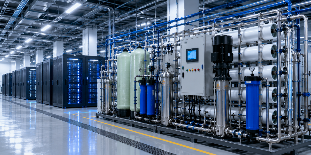
Field Engineering Insight: The Cascade Failure Nobody Predicts—Mixing Treated and Untreated Streams
Here is a real-world failure pattern from a major data center:
A 50 MW facility in Phoenix commissioned a high-capacity RO plant to feed both TCS (direct liquid cooling) and FCS (cooling tower). The system was sized for 150 GPM total output—80 GPM to TCS, 70 GPM to FCS makeup.
Design assumed that even if the RO system went offline, the facility could run cooling tower operations indefinitely on municipal supply bypassing treatment. “Just use the municipal water directly if treatment fails,” the engineering team reasoned.
Week 8 of operation: RO system develops biofilm fouling (ATP monitoring was not installed). Permeate quality degrades: TDS rises from 50 ppm to 180 ppm. The system does not alarm (no conductivity sensors on product water). Makeup flows continue.
Week 10: TCS loop begins showing elevated conductivity (15 µS/cm, above 10 µS/cm safety limit). GPU thermal performance degrades slightly; nobody notices yet.
Week 11: Cooling tower, now receiving makeup water at 180 ppm TDS instead of 50 ppm, begins accumulating silica faster. Anti-scalant program remains fixed-rate (not adjusted for higher silica load). COC control fails.
Week 12: TCS cold plate micro-channels begin showing silica precipitation (first GPU thermal throttling events detected). Simultaneously, cooling tower heat exchanger silica fouling accelerates. Thermal efficiency drops 8–12%.
Week 14: Emergency: GPU cluster is hitting thermal limits despite adequate ambient cooling. Root cause analysis reveals: RO product water quality degradation propagated into both TCS and FCS, creating a cascade failure.
Prevention: Install conductivity sensors on RO product water with alarm at >75 µS/cm. When alarm fires, automatically divert RO product to blowdown recovery (where 180 ppm TDS is acceptable) and trigger notification to ops. Activate backup RO train (if N+1 exists) or place facility on water conservation mode (reduce cooling tower makeup, shift load if possible).
The lesson: Even well-intentioned “bypass to untreated water” contingencies fail because treated and untreated pathways cannot be safely mixed. Design for redundancy—not for graceful degradation.
ASHRAE TC 9.9 and EPA Compliance: The Non-Optional Framework
Any data center deploying direct liquid cooling or blowdown recovery now operates under explicit regulatory and industry-standard mandates.
ASHRAE TC 9.9 (Liquid Cooling White Paper):
Mandatory water quality monitoring for all closed-loop TCS systems:
- Conductivity ≤ 10 µS/cm (target < 5 µS/cm)
- pH 6.5–7.5 (avoid both corrosion and caustic risk)
- Silica ≤ 1.0 ppm
- Copper ≤ 0.05 ppm
- Iron ≤ 0.1 ppm
- Biocide concentration documented (if used)
EPA NPDES Permit Requirements (if cooling tower blowdown exceeds municipal threshold):
Facilities using >10,000 GPD of blowdown must register as industrial dischargers. Blowdown quality is monitored quarterly. Excessive phosphate, silica, or biocide residuals trigger surcharges or enforcement action.
State-level Legionella Mandates (ASHRAE 188 compliance):
All cooling towers above a defined basin volume require a formal Water Quality Management Plan, biocide documentation, and annual risk assessment. Failure to document results in facility closure orders during public health emergencies.
What this means for your facility:
Every data center deploying advanced water treatment must maintain:
- Annual water quality management plan (signed by licensed engineer)
- Quarterly lab analysis reports (retained for 3 years)
- Biocide use logs (documentation of chemical, concentration, date)
- Treatment system maintenance records (membrane replacement, CIP logs)
- DCIM-generated trend reports (conductivity, TDS, flow rates)
Non-compliance carries penalties: $10K–$50K per violation, facility operating licenses at risk in health emergencies.
Frequently Asked Questions
Q1: Should we design a single unified water treatment plant or separate TCS/FCS trains?
Separate trains. A unified plant attempting to produce water suitable for both ultra-pure TCS (≤ 10 µS/cm) and standard FCS makeup (~100 µS/cm) will over-treat FCS (wasting energy/chemicals) and under-treat TCS (increasing corrosion risk). Two smaller, purpose-built systems cost ~$80K more but eliminate cross-contamination risk and extend membrane life 3–5×.
Q2: What redundancy architecture is required for Tier III vs. Tier IV facilities?
Tier III minimum: N+1 (duty/standby) on critical stages (RO, softener, EDI). Automatic switchover required; operator intervention not acceptable. Tier IV: 2N (two fully independent trains, each sized for 100% demand). No shared components. Both trains run continuously at 50% load; failure of one triggers automatic scale-up of remaining train to 100%.
Q3: How do we handle three different source waters (municipal, reclaimed, process returns) in a single facility?
Design three separate pre-treatment trains with different stage sequences. Municipal: standard softening + RO. Reclaimed: coagulation + UF + RO (derated recovery). Process returns: pre-filtration + UV + ion-exchange. Convergence point: post-treatment polishing (cartridge filter + final conductivity check) before TCS or FCS distribution.
Q4: What BMS monitoring parameters are non-negotiable for mission-critical uptime?
Real-time DCIM integration (15-min polling): RO inlet/outlet TDS, ΔP, flow rate, recovery % (calculated), anti-scalant pump rate, concentrate conductivity, system runtime hours, temperature sensors. Automated alarms at setpoints. Continuous trending for predictive maintenance (membrane replacement at 24 months or when flux declines >20%).
Q5: How often should water quality lab sampling occur, and what parameters are critical?
Quarterly minimum for EPA compliance (if >10,000 GPD blowdown). Parameters: TDS, conductivity, silica, hardness, copper, iron, pH, biocide residual (if applicable), biological activity (ATP for Legionella risk). For mission-critical facilities, monthly sampling provides better trend visibility and earlier warning of treatment system degradation.
Q6: What is the business case for N+1 or 2N redundancy if the facility can “just shut down” if water treatment fails?
Shutting down is not an option. A 50 MW hyperscale facility loses $500K–$2M per day of downtime. N+1 redundancy costs ~$80K–$150K capex; the ROI is <1 month (avoided single outage). 2N redundancy costs ~$200K more but guarantees zero facility downtime from water treatment failure—non-negotiable for mission-critical SLA contracts with cloud tenants.
Q7: Are there any ASHRAE TC 9.9 or EPA compliance shortcuts we can take?
No. Non-compliance results in facility shutdown orders and penalties of $10K–$50K per violation. The compliance costs (lab sampling, documentation, annual audits) are minimal (~$8K/year) compared to the cost of non-compliance. Budget for annual certification and maintain full audit trails.
Integrate Industrial Water Treatment Into Your Mission-Critical Infrastructure Plan
Industrial water treatment for AI data centers is not a commodity utility—it is a mission-critical system that determines whether your facility achieves 99% uptime or 99.999% uptime.
The difference between a standard industrial plant and a data center-grade system is not complexity for complexity’s sake. It is the systematic elimination of every single-point failure, the integration of redundancy at every critical stage, and the adoption of real-time monitoring that transforms reactive troubleshooting into predictive maintenance.
Your cooling infrastructure—TCS cold plates, CDUs, cooling towers, and chillers—depends entirely on the water quality delivered by your treatment system. Undersizing redundancy, overspecifying recovery rates, or ignoring multi-source water chemistry will trigger expensive cascading failures within months of commissioning.
Contact YourWaterGood for a mission-critical water system architecture consultation:
- Facility-specific system design: Separate TCS/FCS trains, source-water adaptive pre-treatment, N+1 or 2N redundancy architecture
- Multi-source water integration: Municipal, reclaimed, and process-return water compatibility analysis
- ASHRAE TC 9.9 + EPA compliance documentation: Annual water quality management plan, biocide registration, NPDES permit support
- BMS integration specification: Real-time DCIM parameter logging, automated alert logic, predictive maintenance triggers
- B2B factory-direct pricing: Complete skid packages with membrane selection, instrumentation, redundancy switchover logic, and 5-year technical support
Request a Mission-Critical Water System Architecture Consultation →
Submit your facility’s MW capacity, current water treatment setup (if any), source water TDS data, target uptime SLA (99.9%, 99.99%, 99.999%), and any known compliance requirements. A comprehensive system design with redundancy architecture, capex/opex analysis, and compliance roadmap will be returned within 48 business hours.