
Cycles of Concentration Optimization for AI Data Center Cooling Towers: Makeup Water Ceilings and Blowdown Control

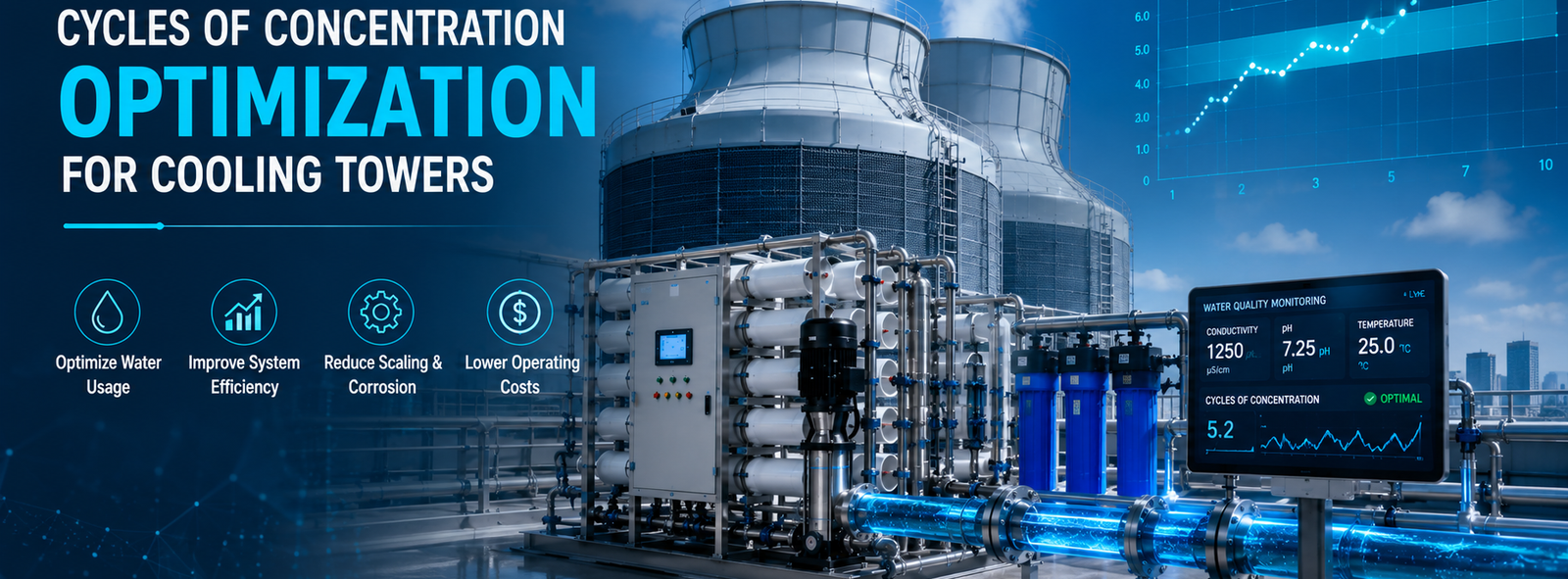
Before a makeup water vendor gets anywhere near your cooling tower basin, lock down these criteria:
- A written makeup TDS ceiling, not a vague “low TDS” promise — a real ppm number, such as under 20 ppm single-stage RO or under 10 ppm two-stage
- Automated blowdown control tied to online basin conductivity, not a manually cracked bleed valve
- A site-specific silica and hardness review before any target cycle count is quoted — a generic “run at 6 cycles” number means nothing without your actual makeup water chemistry
- Pretreatment matched to source water type: chloride-resistant design for municipal supply, high-TDS/silica-resistant design for reclaimed or recycled makeup
- Continuous duty-cycle GPM capacity sized to worst-case evaporation load at full rack density — not an average-day estimate
Get any of these wrong and the tower either wastes water it didn’t need to lose, or scales a heat exchange surface the facility can’t afford to lose.
Fast Check Product: https://yourwatergood.com/product/industrial-reverse-osmosis-system/
What Cycles of Concentration Actually Controls in a High-Density Loop
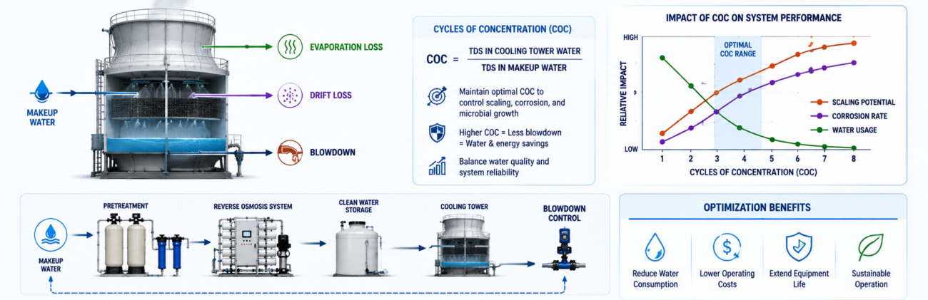
Cycles of concentration (COC) describes how much more concentrated dissolved solids become in the recirculating tower water compared to the makeup water feeding it. Pure water leaves as vapor during evaporative cooling; the minerals it carried stay behind and build up in the basin.
Per U.S. Department of Energy figures, most cooling towers in the field still run in the 2–4 cycle range. Moving from three cycles to six cuts makeup water consumption by roughly 20% and blowdown volume by roughly half — without touching tower capacity or fan energy.
For a facility running cycles of concentration optimization for cooling towers as a deliberate program rather than a default setting, the payoff compounds at AI-cluster scale: less makeup water pulled per ton of heat rejected, less blowdown discharged, and fewer basin cleanings that take capacity offline during peak thermal load.
The engineering risk runs the other direction, though — a tower pushed past its makeup water’s actual ceiling scales the fill media and heat exchange surfaces before conductivity alarms even register the problem, quietly raising approach temperature and eating into the thermal margin a high-density GPU row depends on.
The Makeup Water Ceiling: Why TDS at the Fill Line Sets Your Practical Maximum
Every basin has a dissolved-solids limit before scaling or corrosion risk becomes unacceptable for a given metallurgy and chemical treatment program. Makeup water TDS decides how many cycles you can run before the recirculating water reaches that limit.
Raw or lightly treated makeup, typically in the hundreds to low thousands of ppm TDS depending on source, hits the basin ceiling fast — often within the 2–4 cycle range most towers default to.
Softened makeup removes hardness but does little to gross TDS, buying some scaling headroom without meaningfully raising the achievable cycle count.
RO-treated makeup changes the ceiling directly. On a five-stage platform bringing raw water from roughly 1,300 ppm TDS down to under 20 ppm single-stage, or under 10 ppm two-stage, the basin has far more room to concentrate before hitting the same TDS limit — which is the entire mechanism behind higher achievable cycles.
This isn’t a formula to run on a spreadsheet before every shift change — it’s a design conversation to have once, with your actual makeup water analysis, before a target cycle count gets written into the operating procedure.
Municipal Water vs. Data Center Reclaimed Water: Two Different Pretreatment Problems
Not every makeup source poses the same risk profile, and pretreatment has to be engineered for the source it’s actually seeing.
Municipal supply carries residual chlorine or chloramine for disinfection. Left untreated ahead of an RO membrane, that residual oxidizes the membrane surface over time. It also raises chloride load in the recirculating loop as cycles increase, which accelerates pitting corrosion on stainless and copper alloy tower components. Pretreatment here leans on activated carbon dechlorination ahead of the membrane stage.
Reclaimed or recycled water, increasingly specified for data center cooling towers to hit site-level water usage effectiveness (WUE) targets, is a different chemistry problem entirely. Baseline TDS runs higher, and dissolved silica is frequently the binding constraint rather than hardness — soluble silica has its own solubility ceiling, and once cycles push past it, silica precipitates as a hard, glass-like scale that doesn’t respond to the same descaling approach as calcium carbonate.
A treatment train built for reclaimed water needs the softening and RO stages doing real work on both fronts simultaneously, not a system sized around municipal-water assumptions and retrofitted after the fact.
Request a Cooling Tower Water Savings Assessment if your site is evaluating reclaimed water as a makeup source — the achievable cycle count with reclaimed water is rarely the same number your municipal-water baseline would suggest.
Softening Alone vs. Softening + RO: Two Different Ceilings on Achievable Cycles
Ion-exchange softening (salt-box regenerated) removes calcium and magnesium hardness, which addresses one scaling mechanism but leaves gross TDS and silica largely untouched. A softened-only makeup stream can push cycles modestly above the 2–4 cycle default, but the basin still hits its overall TDS or conductivity blowdown limit relatively early.
Pairing softening with RO — the same five-stage sequence (multimedia filter → activated carbon → ion-exchange softening → precision security filter → RO membrane array) — pulls hardness, silica, and gross TDS down together, which is what actually clears room for a materially higher cycle target.
Modular platforms sized 4.4 to 44 GPM (1–10 t/h), with a minimum 29 PSI (0.2 MPa) inlet pressure requirement, scale makeup capacity to match tower evaporation load without over- or under-sizing the skid for the site’s actual duty cycle.
Request a Data Center Water Sizing Consultation to match makeup GPM, target TDS, and your site’s realistic cycle ceiling against a modular skid configuration before basin chemistry gets locked into an operating procedure.
Field Engineering Insight: Why Overshooting Cycles Is a Cold Plate Problem, Not Just a Basin Problem
Silica scale that forms past the solubility ceiling doesn’t stay politely in the tower basin. Fine particulate and colloidal silica fractions carry downstream through the condenser water loop and, on sites where cooling tower water interfaces with CDU secondary loops or heat exchangers feeding a cycles of concentration optimization for cooling towers program, that same fouling risk shows up at heat exchange surfaces sized to much tighter tolerances than the tower fill itself — including cold plate microchannels running under 100 microns in current-generation accelerator designs.
The second detail worth building into any cycle target: RO membrane flux drops as feed water temperature falls, so a system rated for a given GPM output in summer will produce less permeate at the same feed pressure in winter. Sites that size makeup capacity only against summer conditions routinely find themselves short of makeup water — and tempted to run cycles higher than the design basis allows — exactly when winter feed temperatures cut permeate output the most.
Standard Pre-Engineered Skids vs. Data Center–Grade High-Redundancy Systems
| Parameter | Standard Pre-Engineered Skid | Data Center–Grade High-Redundancy System |
|---|---|---|
| Flow control | Fixed GPM band, manual valve trim | Automated GPM trim across parallel trains |
| Redundancy | Single train (N); service requires downtime | N+1 or 2N parallel trains; hot-swap capable |
| BMS / SCADA integration | Local PLC + HMI, standalone alarms | PLC-to-BMS/SCADA handoff, remote alarm escalation, historian logging |
| Blowdown / COC control | Manual or basic conductivity setpoint | Automated basin conductivity control tied to blowdown valve, trend logging per train |
| Delivery lead time | Shorter — standard configuration | Longer — engineered-to-order for site redundancy |
| Filtration precision | 5-stage baseline (multimedia → carbon → softening → security filter → RO) | Same 5-stage baseline, duplexed critical components, tighter alarm bands |
A standard skid is frequently the right call for a single-tower retrofit targeting a modest cycle increase. Multi-tower hyperscale sites chasing an aggressive WUE target with reclaimed water in the mix tend to need the automated blowdown and historian logging that only the higher-redundancy configuration carries as standard scope.
FAQ
What is cycles of concentration and why does it matter for AI data center cooling towers? It’s the ratio of dissolved solids concentration in the recirculating tower water compared to the makeup water; running it higher directly reduces both makeup water draw and blowdown discharge per ton of heat rejected.
How much water can raising cycles of concentration actually save? Per DOE figures, moving from roughly three to six cycles cuts makeup water consumption by about 20% and blowdown volume by about 50%, without any change to tower capacity.
What makeup water TDS is needed to reliably hit 6+ cycles of concentration? It depends on your basin’s specific TDS or conductivity blowdown limit, but single-stage RO makeup under 20 ppm TDS (or under 10 ppm two-stage) gives materially more headroom than softened-only or raw makeup in the hundreds-to-thousands of ppm range.
Does reclaimed or recycled makeup water limit achievable cycles of concentration? Often, yes — reclaimed water typically carries higher baseline TDS and dissolved silica than municipal supply, and silica’s own solubility ceiling frequently becomes the binding constraint before hardness does.
Does softening alone get a cooling tower to a high cycle target, or is RO required? Softening addresses hardness-driven scaling but leaves gross TDS largely unchanged; reaching a materially higher cycle target generally requires RO layered on top of softening, not softening by itself.
How does raising cycles of concentration affect discharge compliance? Higher cycles reduce blowdown volume, which lowers the total TDS, chloride, and treatment-chemical load discharged under local sewer or NPDES permit limits — a direct compliance benefit alongside the water savings.
Does a standard RO skid handle both municipal and reclaimed water sources? The core five-stage architecture applies to both, but pretreatment emphasis shifts — chloramine/chlorine resistance and corrosion control for municipal sources, and stronger silica/TDS reduction capacity for reclaimed sources — so source water should be specified before sizing.
Setting a cycle target that actually holds up under a full year of feed water variation — not just a summer commissioning test — starts with real numbers: an Infrastructure Engineering Quote sized to your makeup GPM and target TDS, full Technical Data Sheets for your mechanical team’s basin chemistry review, and B2B wholesale / factory-direct pricing on the skid and control package. Request all three before your next cycle target gets written into an operating procedure.