Industrial Water Purification System: Engineering the CAPEX/OPEX Balance for 24/7 Production

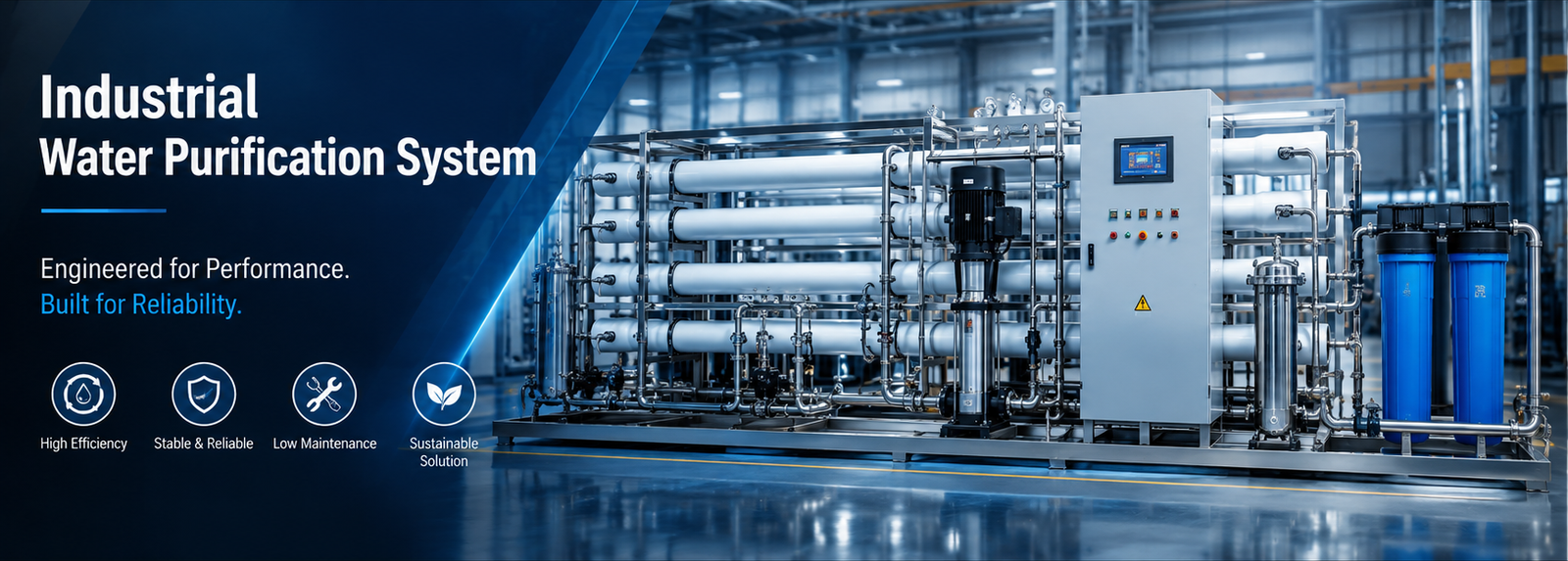
A single TDS spike from a municipal main, or a heavy-metal exceedance from a deep well feed, can put an entire production shift at risk within hours. For facilities running continuous duty cycles, water-quality variation isn’t a lab footnote — it’s a downtime line item that reaches the P&L.
Before evaluating any vendor, lock these specs first:
- Continuous duty-cycle rating validated against your actual peak GPM demand, not a nameplate capacity figure.
- Automated CIP (clean-in-place) integration so membrane cleaning doesn’t require a production stoppage.
- A temperature-correction margin built into membrane sizing, not just a headline GPD number.
- 316L stainless steel or high-grade UPVC wetted materials rated for continuous high-PSI operation.
- PLC-based automation with real-time PSI and flow monitoring for predictive maintenance, not manual gauge checks.
Sourcing a properly engineered industrial water purification system means locking these five items into the RFP before a single quote comes back — not discovering the gaps after the skid is on site.
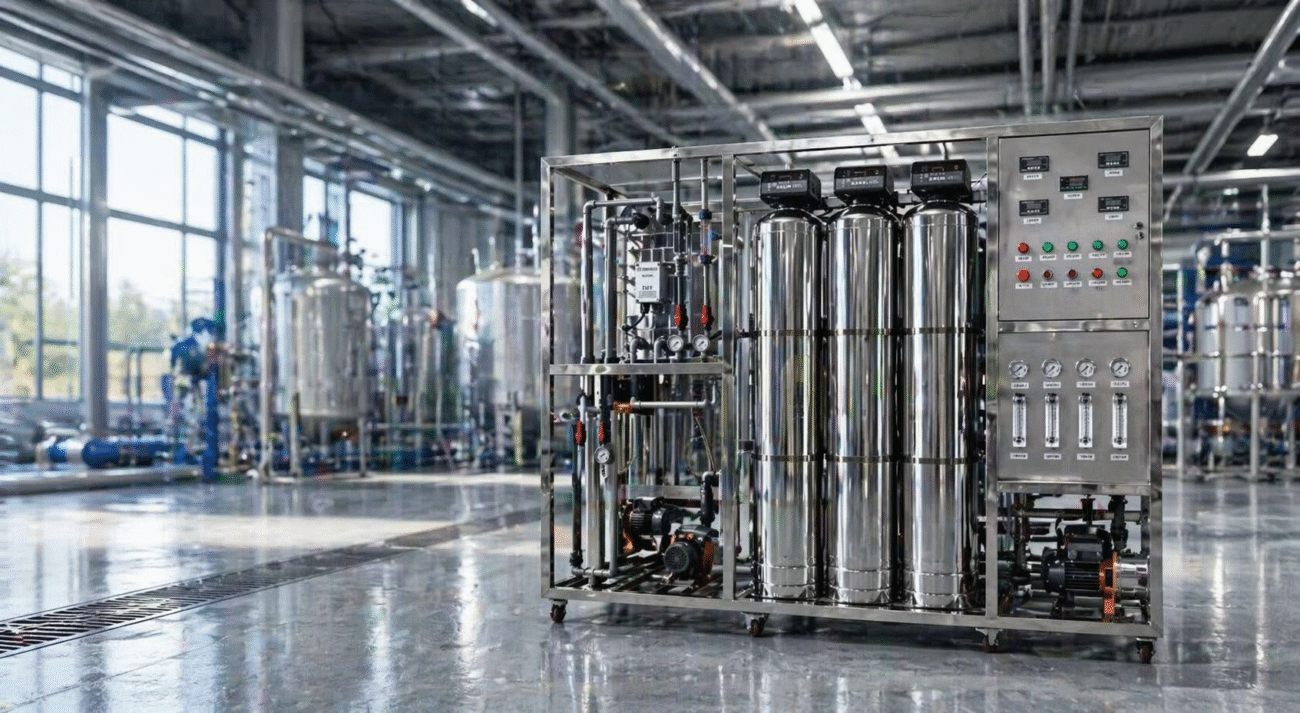
Fast Check Product: https://yourwatergood.com/product/industrial-reverse-osmosis-system/
Municipal vs. Deep Well Feed: Two Different Pretreatment Problems
Feed water source dictates pretreatment architecture. Treating the two the same way is the most common sizing error we see.
Municipal potable feed:
- Predictable chemistry, but chlorine and chloramine will oxidize RO membranes if not stripped upstream.
- Soluble inorganic salts drive the RO sizing baseline; carbon filtration protects the membrane, not the process.
Deep well feed:
- Higher variability. Hardness, dissolved iron and manganese, and silica (SiO₂) each require a dedicated removal step — softening, oxidation/filtration, or antiscalant dosing — before water reaches the RO array.
- Well chemistry shifts seasonally, so the pretreatment design margin has to account for that swing, not just a single water-analysis sample.
A resilient system architecture typically runs a five-stage sequence: a multimedia filter for suspended solids, an activated carbon filter for chlorine and organics, an ion-exchange softening stage to eliminate hardness scaling, a precision security filter as the final particulate barrier, and the RO membrane array itself. Each stage exists to protect the one after it — undersizing the multimedia stage is how a security filter ends up changed every two weeks instead of every quarter.
This pretreatment logic sits inside the broader EPA Water Quality Framework governing industrial discharge and process-water handling, which is worth reviewing during the design phase rather than after commissioning.
Sizing the System: Flow Capacity, TDS Rejection, and Inlet Pressure
Capacity planning starts with real production demand, not a rounded-up guess.
- Flow capacity: Modular skids typically scale from roughly 4 GPM to 44 GPM (approximately 6,300–63,400 GPD) per train, with multi-train configurations engineered for higher-demand facilities.
- TDS rejection: In documented field cases, raw feed TDS has been reduced from 1,300 ppm to under 20 ppm in single-pass configurations, and to under 10 ppm in two-pass setups — the achievable rejection rate depends entirely on raw water chemistry, so a water analysis should always precede a spec commitment.
- Inlet pressure: RO booster pumps are engineered to operate against a minimum inlet pressure of roughly 0.2 MPa (~29 PSI). Sites running below that threshold need a pre-boost pump stage specified up front, not added as a change order.
- Wetted materials: Thickened membrane housings paired with 316L stainless steel or high-grade UPVC piping are what sustain continuous high-pressure operation without the pitting that shortens skid life in chloride-heavy feed water.
Request a Custom CAD Skid Diagram or Water Analysis Review before finalizing GPM targets — sizing against a real water report, not a generic assumption, is what keeps the membrane warranty valid.
Standard Pre-Engineered Skids vs. Fully Customized Turnkey Systems
Not every packaged RO skid is engineered the same way. The table below is what actually separates a catalog skid from a true turnkey system.
| Engineering Parameter | Standard Pre-Engineered Skids | Fully Customized Turnkey Systems |
|---|---|---|
| Flow capacity (GPM) | Fixed, single-train sizing | Custom-sized, multi-train scalable |
| CAPEX structure | Lower upfront, component-based | Higher upfront, single consolidated price |
| Lead time | Shorter — built to stock configurations | Longer — engineered to site-specific water analysis |
| PLC integration | Basic relay logic or standalone HMI | Siemens or Allen-Bradley platform, SCADA-ready |
| Redundancy | Typically none — single point of failure | N+1 or 2N engineered across the train |
A standard skid fits a facility with stable, well-characterized feed water and modest uptime requirements. A fully customized turnkey system fits a facility where an unplanned outage costs more in a single shift than the CAPEX premium.
Automation and Uptime: PLC Control, Auto CIP, and Predictive Maintenance
The intelligence layer is what determines total cost of ownership, not the membrane count.
- Automatic backwash and flushing cycles maintain flux and prevent membrane blinding without an operator initiating every cycle manually.
- Real-time PSI and flow monitoring feeds a PLC control loop — Siemens or Allen-Bradley platforms are the industrial standard here — so pressure drift is caught before it becomes a fouling event.
- Auto CIP (clean-in-place) lets the system clean membranes on a defined schedule without disassembling the skid or halting the production line to do it.
This automation layer is what protects the capital equipment sitting downstream of the water system: boilers, heat exchangers, and cooling towers all see fewer emergency descaling cycles when the feed water quality holds steady through every shift, every season, at true 24/7/365 duty.
Field Engineering Insight: Cold-Water Flux Decay and Antiscalant Dosing Logic
Here’s the detail that separates a system that survives its first winter from one that doesn’t.
When well water temperature drops toward 50°F (10°C), water viscosity increases measurably. If the design didn’t account for this with a temperature correction factor — typically 30%–40% additional membrane area built in at the sizing stage — the system can’t hit its rated GPD output at that lower temperature without compensating elsewhere.
The compensation usually happens the wrong way: the high-pressure pump gets pushed to a higher PSI to force the same flow through membranes that are now less efficient. That drives energy consumption up, and it accelerates scaling and fouling on the membrane surface — especially if the antiscalant dosing pump wasn’t calibrated to the feed water’s actual silica and calcium concentration in the first place.
Left uncorrected, this combination — under-sized membrane area plus miscalibrated dosing — can drop production output enough within a single week that the line goes down. It’s rarely diagnosed as a design flaw; it usually gets logged as “unexplained membrane fouling.”
Where Water Quality Consistency Becomes a Production Requirement
Industrial water purification systems built on this five-stage architecture serve a consistent set of high-standard sectors:
- Food & beverage production — sterile, consistent ingredient and process water for manufacturing lines.
- Medical and laboratory environments — low-conductivity purified water for sensitive testing and formulation work.
- Livestock and agriculture operations — mineral-balanced water supply at scale.
- Metal processing and precision manufacturing — protecting machinery from corrosion and mineral deposits during industrial cleaning cycles.
For food, beverage, and lab-adjacent production, system architecture can be engineered toward the conductivity and purity targets referenced in FDA and USP Purified Water frameworks — typically by pairing the RO stage with EDI or mixed-bed polishing downstream. That’s a design target the engineering team sizes toward, not a claim about any specific facility’s regulatory status, which depends on the buyer’s own quality program and validation process.

Industrial Water Purification System FAQs
What flow capacity does an industrial water purification system need for a manufacturing facility? Most modular skids cover 4–44 GPM (roughly 6,300–63,400 GPD) per train. Facilities above that range typically move to multi-train, custom-engineered configurations rather than a single oversized skid.
What’s the difference between a standard skid and a custom turnkey system? A standard skid is fixed-capacity and built to stock; a turnkey system is sized to your actual water analysis, includes PLC/SCADA integration, and is engineered with redundancy (N+1 or 2N) across the train.
How much TDS can an industrial reverse osmosis system remove? In documented cases, raw feed TDS has been reduced from 1,300 ppm to under 20 ppm in a single pass, and under 10 ppm in a two-pass configuration. Actual rejection depends on raw water chemistry.
What inlet water pressure does an industrial RO system require? A minimum of roughly 0.2 MPa (~29 PSI) at the booster pump inlet. Sites below that threshold need a pre-boost pump stage specified at design time.
Does cold well water reduce membrane performance? Yes. Below 50°F (10°C), viscosity increases enough to reduce flux. Systems designed without a temperature correction factor (typically 30%–40% extra membrane area) tend to compensate with higher PSI, which accelerates scaling.
What materials should the skid piping and membrane housings be built from? 316L stainless steel or high-grade UPVC piping with thickened membrane housings, sized for continuous high-pressure operation and resistance to chloride-driven pitting.
Can an industrial RO system meet FDA/USP purified water targets? The architecture can be engineered toward USP-referenced conductivity and purity targets when RO is paired with EDI or mixed-bed polishing. Meeting a specific regulatory status still depends on the buyer’s own validation and quality program.
Get an Engineered Quote for Your Production Line
Sizing an industrial water purification system against a real water analysis — not a catalog spec sheet — is what protects the membrane warranty and the production schedule behind it.
- Get an Industrial Engineering Quote: send your water analysis and flow requirement for a sized proposal.
- Request Technical Data Sheets & P&ID Drawings: get the full engineering submittal package for your project file.
- Get B2B Wholesale / Factory-Direct Pricing: request competitive pricing sourced through our vetted manufacturing network.
Whether the requirement is a single skid or a multi-train build, the industrial water purification system architecture above is engineered to hold flux, hold pressure, and hold uptime — through every season, not just the ones with warm well water.