
Industrial RO System for Data Centers: Matching Membrane Configuration to Feed-Water Chemistry

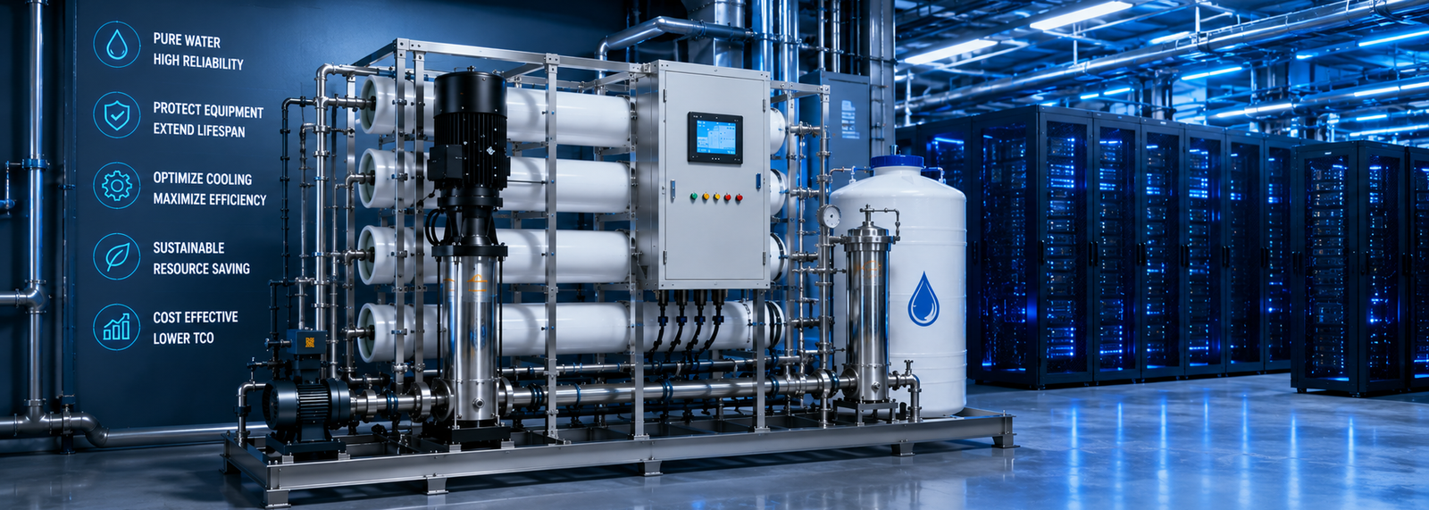
An industrial RO skid that performs flawlessly on a Phoenix reclaimed-water site will under-reject — or scale itself shut — on an Ashburn municipal feed, even at an identical flow rating. The variable that decides the outcome is not capacity. It is whether the membrane configuration was matched to the feed-water chemistry.
Two facilities can buy the “same” 10 t/h RO, run it on different source water, and get completely different conductivity, recovery, and membrane life. One holds ≤ 10 µS/cm to a direct-to-chip loop for years; the other fouls in months.
Specifying an industrial ro system for data centers correctly means engineering the pass count, membrane element, and array around the water that actually enters the skid — not around a generic datasheet.
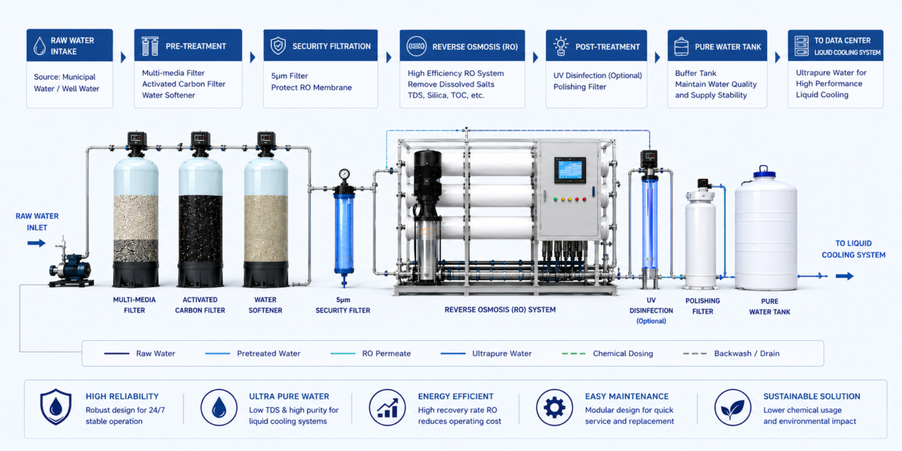
Engineered to transform highly contaminated source water into ultrapure process water that satisfies rigid data center infrastructure metrics, the commercial and industrial treatment platforms from YourWaterGood utilize a highly resilient five-stage pre-treatment and modular desalination sequence:
- Stage 1: Multimedia Filtration (Sand Filter): Intercepts large-scale physical suspended solids, clay, rust, and silt to safeguard downstream membrane lifespans.
- Stage 2: Activated Carbon Filtration: Deeply adsorbs residual chlorine, organic compounds, and unwanted color or odors, preventing oxidative breakdown of sensitive reverse osmosis elements.
- Stage 3: Ion-Exchange Softening & Scale Inhibition: Equipped with automated control valves and integrated scale inhibition dosing, this module extracts hardness ions (Calcium and Magnesium) to completely eliminate crystallization risks inside primary heat exchangers.
- Stage 4: Precision Security Filtration (Micron Filter): Serves as a definitive physical boundary to catch any remaining micro-particulates before water enters the high-pressure membrane array.
- Stage 5: Dual-Pass Reverse Osmosis (RO) Membrane Core: Utilizes thickened membrane housings and high-grade stainless steel or UPVC piping to execute high-pressure molecular separation, achieving an exceptional salt rejection profile.
Downstream Polishing: Continuous Electrodeionization (EDI)
For mission-critical direct-to-chip loops requiring deep demineralization, the system integrates an advanced EDI module downstream of the secondary RO stage. As a green water treatment technology, EDI offers distinct engineering advantages over legacy mixed-bed resin cylinders:
- Chemical-Free Operations: EDI utilizes a continuous electrical current to regenerate its ion-exchange resins internally, completely eliminating the operational downtime, labor, and environmental hazards associated with acid and alkali chemical regeneration.
- Uninterrupted Water Quality: While conventional mixed beds suffer from purity fluctuations during exhaustion and regeneration cycles, the EDI water production process remains completely continuous and stable, delivering a constant ultrapure output.
- Compact, Modular Footprint: Built on a space-saving, stackable modular architecture, the EDI array can be flexibly configured to match on-site facility height and clearance restrictions, greatly simplifying long-term preventative maintenance.
Fast Check Product:https://yourwatergood.com/product/industrial-reverse-osmosis-system/
Before sourcing, lock these configuration specifications first:
- Pass count set by purity target — single-pass for cooling-tower (FWS) makeup; two-pass plus EDI to reach the ≤ 10 µS/cm a technology cooling system (TCS) requires.
- Membrane element matched to feed — high-rejection elements for high-TDS; fouling-resistant brackish-water elements for reclaimed or high-organic feed.
- Recovery rate driven by feed chemistry, not a spec-sheet default — high-TDS feed runs 65–75%, not an aspirational 80%+.
- Pass-2 pH elevation capability where reclaimed feed carries high silica or boron, with hardness removed first.
- 316L wetted parts, VFD high-pressure pumps, and BMS telemetry — conductivity, ΔP (PSI), and flow (GPM) into Modbus TCP or BACnet IP.
The sections below break down each configuration decision and where it fails on the floor.
Single-Pass vs Two-Pass: How the Purity Target Sets the Architecture
The first configuration decision for any industrial ro system for data centers is pass count, and it is dictated entirely by which loop the permeate feeds.
Single-pass RO is sufficient for the Facilities Water System (FWS) — open cooling towers and condenser water. A single pass on typical municipal feed drops TDS (ppm) by roughly 95–99% and delivers makeup clean enough to run high Cycles of Concentration (CoC) without aggressive scaling.
Two-pass RO becomes mandatory for the Technology Cooling System (TCS) — closed direct-to-chip loops. A single pass cannot reliably hold the ≤ 10 µS/cm conductivity that protects copper cold plates from galvanic attack, so the first-pass permeate is fed to a second pass for final demineralization.
The full purity ladder for a direct-to-chip loop:
- Pass 1: bulk demineralization, TDS down ~99%.
- Pass 2: polishing the first permeate to roughly 1–5 µS/cm.
- EDI: continuous electrodeionization driving output toward ≤ 0.1 µS/cm and up to 18.2 MΩ·cm resistivity, with no chemical regeneration.
Specifying a single-pass skid for a TCS loop is the most common architecture error on a data center project. It looks adequate at commissioning and then drifts above the conductivity limit as membranes age — the purity target, not the flow rate, sets the pass count.
Membrane Selection by Feed Chemistry: High-TDS vs High-Silica vs Reclaimed
Two RO skids with identical flow ratings can carry completely different membrane elements, because the element chemistry has to be matched to the dominant fouling and rejection challenge in the feed.
High-TDS municipal or brackish feed:
- Use high-rejection brackish-water (BW) elements to maximize salt rejection per pass.
- Pair with antiscalant dosing sized to the specific hardness and alkalinity profile.
High-silica feed (common in Phoenix-area groundwater):
- Silica is weakly ionized and poorly rejected at neutral pH; standard elements let it slip into the permeate.
- The combination of fouling-resistant elements, antiscalant, and pass-2 pH elevation (covered below) is what actually controls it.
Reclaimed and recycled feed:
- High organic load, phosphate, and ammonia foul standard elements quickly.
- Use fouling-resistant elements with wider feed channels and assume shorter cleaning intervals when projecting OPEX.
The wrong element is an expensive mistake in both directions: a high-rejection element on heavily fouling reclaimed water blinds fast, while a fouling-resistant element on clean high-TDS feed under-rejects. The element is selected against the water analysis, never ordered off a generic model number.
Array Staging and Recovery: Configuring the RO Block Itself
Beyond pass count and element type, the physical arrangement of pressure vessels — the array — determines how much product water the skid recovers and how evenly the membranes wear.
A typical brackish array uses a staged (tapered) configuration, such as a 2:1 arrangement: concentrate from the first stage feeds a smaller second stage, maintaining crossflow velocity as volume drops. This holds flux uniform and limits scaling in the tail elements where rejected ions concentrate.
Recovery rate is then set by the feed chemistry, not by ambition:
- High-TDS feed: hold recovery to 65–75%. Pushing higher concentrates sparingly soluble salts past saturation in the tail elements, where they scale first.
- Lower-TDS municipal feed: higher recovery is achievable, but always inside the solubility limits of silica, calcium carbonate, and sulfate.
The interaction that catches inexperienced specifiers: raising recovery shrinks concentrate volume and raises its concentration, accelerating scaling at the membrane tail even when the bulk permeate looks clean. A skid configured for an aggressive recovery number on the wrong feed trades a smaller reject stream for a shorter membrane life — and higher cleaning OPEX.
Municipal vs Reclaimed Feed: Two Different RO Front-Ends
The pre-treatment ahead of the RO block is not interchangeable between source types. Municipal and reclaimed feeds demand fundamentally different front-end architectures.
Municipal potable feed carries chlorine and chloramine that oxidize and destroy thin-film membranes. The front end centers on:
- Activated carbon adsorption to remove oxidizers ahead of the membranes.
- Chloride control, since chlorides above low thresholds drive pitting corrosion on 316L under high-velocity flow.
Reclaimed and recycled feed — increasingly mandated for WUE targets — arrives with high TDS, silica, phosphate, ammonia, and organics. Its front end is heavier:
- Multimedia filtration for suspended solids and turbidity.
- Skid-mounted ion-exchange softening with automated brine regeneration to strip hardness.
- Antiscalant dosing ahead of the high-pressure stage, because silica above ~150 ppm polymerizes into a glassy scale no acid wash removes once set.
- Fouling-resistant membranes and, frequently, pass-2 pH elevation.
A skid front-end engineered for municipal feed will run short and foul early on reclaimed water. Source water is locked before the RO configuration, not after.
Standard Skids vs Data-Center-Grade RO Systems
A commercial RO skid is built for one feed, one capacity, and intermittent duty. A data-center-grade industrial ro system for data centers is engineered around the feed analysis, configured for the target loop, and built to run 24/7/365 with redundancy.
| Engineering Parameter | Standard Pre-Engineered Skids | Data Center Grade High-Redundancy RO Systems |
|---|---|---|
| Configuration | Fixed single-pass | Single- or two-pass + EDI, set by loop target |
| Membrane selection | One generic element | Element matched to feed (BW / high-rejection / fouling-resistant) |
| Flow capacity (GPM) | 10–50 GPM | 100–1,000+ GPM, parallel trains |
| Redundancy | Single train | N+1 / N+2 / 2N parallel architecture |
| Output conductivity | ~20–50 µS/cm | ≤ 10 µS/cm (two-pass) → 18.2 MΩ·cm (EDI) |
| Filtration / rejection | 10–20 µm nominal pre-filter | Absolute guard + RO to 0.0001 µm |
| BMS integration | Analog (4–20 mA) | Modbus TCP / BACnet IP / SNMP |
| Lead time & support | Stock unit, generic spares | Engineered build, documented P&ID, standardized spares |
An N+1 RO configuration guarantees that when one train drops for CIP cleaning or membrane replacement, a parallel train ramps instantly and loop conductivity never drifts. That continuity is what underwrites 99.999% uptime at the water plant.
To pressure-test a vendor, ask which membrane element they have specified for your feed analysis and why. A supplier quoting a flow rating without naming the element and pass count is selling a generic skid, not a configured system.
Field Engineering Insight: Pass-2 pH Elevation for Silica and Boron
Here is a detail that separates RO specialists from skid resellers: silica and boron are barely rejected by RO at neutral pH — and the fix is chemistry on the second pass, not a better membrane.
Both silica and boron are weakly ionized in neutral water, so they pass through membranes that reject ordinary salts at 99%+. On a high-silica Phoenix-area feed, a conventionally configured two-pass skid can still deliver permeate that fails the silica limit for a direct-to-chip loop.
The technique experienced engineers apply: raise the pass-2 feed pH to roughly 8.5–9.5 by dosing caustic (NaOH). At elevated pH, silica and boron shift into their ionized forms, and RO rejection of both climbs sharply.
The trap — and why this is a field skill, not a textbook line — is the prerequisite:
- Elevated pH on water that still contains hardness will scale the pass-2 membranes with calcium carbonate almost immediately.
- Hardness must be removed upstream (softening or first-pass rejection plus antiscalant) before the pH is raised.
- Get the sequence wrong and the cure destroys the membranes faster than the silica would have.
This is the kind of configuration detail that never appears on a flow-rated quote but decides whether a high-silica site can hold its loop spec at all. It also protects the assets downstream: stable, low-conductivity permeate lowers cleaning OPEX, keeps cold plates and CDUs free of deposition, holds high-pressure pumps in their efficient curve, and extends the capital life of the entire thermal chain.
Industrial RO System for Data Centers FAQs
Does an industrial RO system for data centers need single-pass or two-pass? Use single-pass for cooling-tower (FWS) makeup. Use two-pass plus EDI to reach the ≤ 10 µS/cm — and up to 18.2 MΩ·cm — that direct-to-chip (TCS) loops require.
Which RO membrane type suits high-silica reclaimed feed? Fouling-resistant brackish-water elements with antiscalant, and frequently pass-2 pH elevation to ionize silica for rejection. High-rejection elements suit clean high-TDS feed, not heavily fouling reclaimed water.
What recovery rate should an industrial RO run on data center feed? For higher-TDS feed, hold recovery to 65–75%. Pushing toward 80%+ concentrates sparingly soluble salts past saturation in the tail elements and accelerates scaling.
How does pass-2 pH elevation improve silica and boron rejection? Raising pass-2 feed pH to roughly 8.5–9.5 with caustic ionizes weakly ionized silica and boron, sharply improving RO rejection. Hardness must be removed first, or the elevated pH scales the membranes.
What conductivity can a two-pass RO plus EDI deliver? Two-pass RO reaches roughly 1–5 µS/cm; EDI polishing drives output to ≤ 0.1 µS/cm and up to 18.2 MΩ·cm resistivity, with no chemical regeneration.
What inlet pressure does an industrial RO skid require? A stable feed above 0.2 MPa (~29 PSI). Where municipal supply fluctuates, a pre-boost pump skid is engineered into the intake to protect membrane flux.
Does municipal feed need a different RO design than reclaimed feed? Yes. Municipal centers on carbon for chlorine/chloramine and chloride control; reclaimed needs heavier multimedia, softening, antiscalant, fouling-resistant membranes, and often pass-2 pH elevation — aligned with ASHRAE TC 9.9 and EPA discharge frameworks.
Configure the Right RO System for Your Feed and Loop
An industrial RO system for a data center is a configuration decision before it is a capacity decision. The skids that hold their loop spec for years are the ones whose pass count, membrane element, and array were engineered around the actual feed-water analysis — not ordered by flow rate alone.
Whether you are equipping a single high-density server room or sourcing trains into a larger buildout, YourWaterGood manufactures and ships the equipment factory-direct — configured industrial ro system for data centers trains, two-pass and EDI polishing, skid-mounted softening, and automated dosing — specified to your water and your loop target.
- Get an Infrastructure Engineering Quote: itemized pricing on configured 1 t/h–10 t/h single- or two-pass RO and EDI matched to your feed analysis.
- Request Technical Data Sheets: rejection curves, recovery, element specs, and BMS integration detail for your engineering review.
- Secure B2B Wholesale / Factory-Direct Pricing: source RO equipment straight from our manufacturing facility.